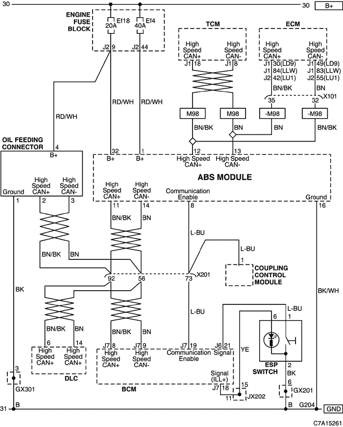
30. ABS (ANTILOCK BRAKE SYSTEM)
1) POWER SUPPLY, OIL FEEDING CONNECTOR, ESP SWITCH, BCM & HIGH SPEED CAN CIRCUIT
a. CONNECTOR INFORMATION
CONNECTOR NO
(PIN NO, COLOR) | CONNECTING WIRING HARNESS | CONNECTOR POSITION |
| X101 (36 Pin, Black) | Engine - Body | Behind the Engine Fuse Block |
| X201 (92 Pin, Black) | Body - I.P | Below to the "A" pillar |
| GX201 (Black/Gray) | I/P | Behind Steering Column - Lower |
| GX301 (Black/Gray) | Body | Under the right seat cushion |
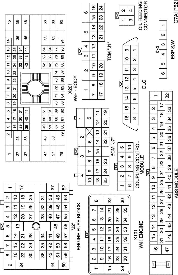
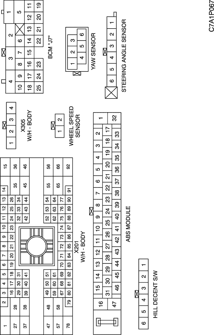
b. CONNECTOR IDENTIFICATION SYMBOL & PIN NUMBER POSITION
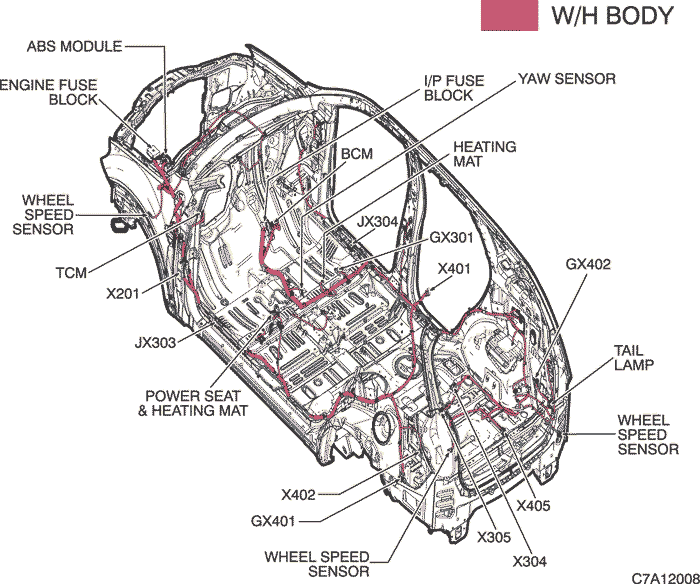
c. POSITION OF CONNECTORS AND GROUNDS
W/H BODY
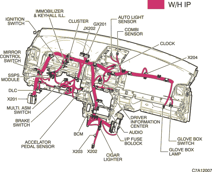
W/H INSTRUMENT PANEL
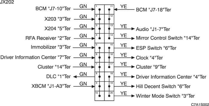
d. SPLICE PACK
JX202 (BLACK/PINK)
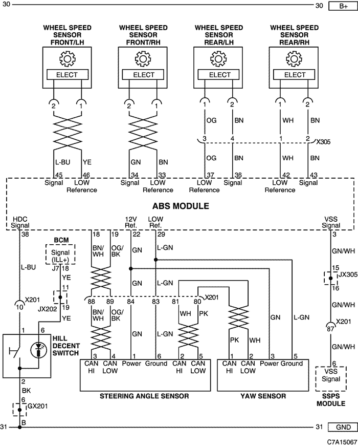
2) SENSOR (WHEEL SPEED, STEERING ANGLE, YAW), HILL DECENT SWITCH & SSPS MODULE CIRCUIT
a. CONNECTOR INFORMATION
CONNECTOR NO
(PIN NO, COLOR) | CONNECTING WIRING HARNESS | CONNECTOR POSITION |
| X201 (92 Pin, Black) | Body - I.P | Below to the "A" pillar |
| X305 (4 Pin, Black) | Body - Rear Wheel Speed Sensor | Behind the "2nd" Seat |
| GX201 (Black/Gray) | I/P | Behind Steering Column - Lower |
b. CONNECTOR IDENTIFICATION SYMBOL & PIN NUMBER POSITION
c. POSITION OF CONNECTORS AND GROUNDS
W/H BODY
W/H INSTRUMENT PANEL
d. SPLICE PACK
JX202 (BLACK/PINK)
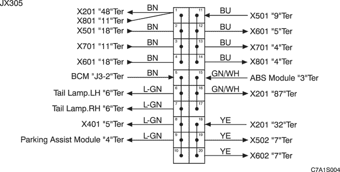
JX305 (BLACK)
| © Copyright Chevrolet Europe. All rights reserved |