MAINTENANCE AND REPAIR
ON-VEHICLE SERVICE
Fuel Priming
Important : In order for the VM2.0S diesel fuel system to work properly, the fuel lines must be full of fuel and contain no air. If air gets into the fuel lines, it will be necessary to prime the fuel system to eliminate the air before operating the vehicle. Air could have entered the system in one of the following ways:
- The vehicle ran out of fuel.
- The filter was removed for service or replacement.
- The fuel lines were removed or disconnected for servicing.
- The fuel pump was removed for servicing.
- The fuel filter water drain cock was opened while the engine was running.
If one or more of the above occurred, air has entered the fuel system and you will need to prime the system prior to operating the vehicle.
- Turn the ignition key ON at 5-second intervals.
Caution : Do not turn the ignition key START. It could be damaged to injection pump.
- Turn the ignition key OFF and wait 3 seconds.
- Repeat procedure No.1 ~ 2 at 6 or 7 times.
Notice : You can do fuel priming work using by SCAN tool.
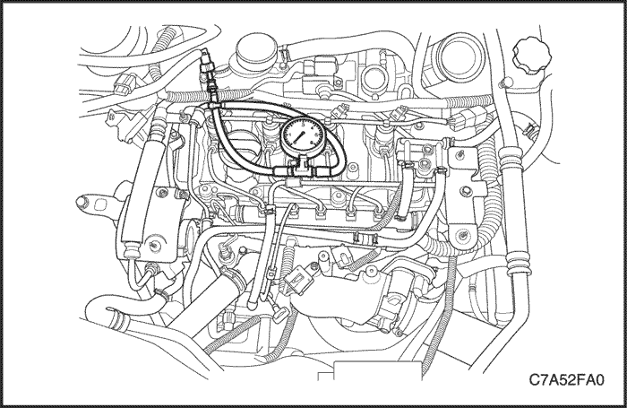


Fuel Pressure Inspection (Low Pressure Line)
Tools Required
DW100-010 Fuel Pressure Gauge
Inspection Procedure
Caution : The fuel system is under pressure. To avoid fuel spillage and the risk of personal injury or fire, it is necessary to relieve the fuel system pressure before disconnecting the fuel lines.
- Disconnect the fuel feed line connector.
- Connect the fuel pressure gauge DW100-010 to the fuel feed line connector.
- Check the fuel leakage.
- Read the fuel pressure gauge DW100-010. Normal fuel pressure is 415kPa (60.2 psi) ~ 535 kPa (77.6 psi).
- Remove the fuel pressure gauge DW100-010.
- Connect the fuel feed line to the fuel rail.
- Do work the fuel priming. Refer to “Fuel Priming” in this section.
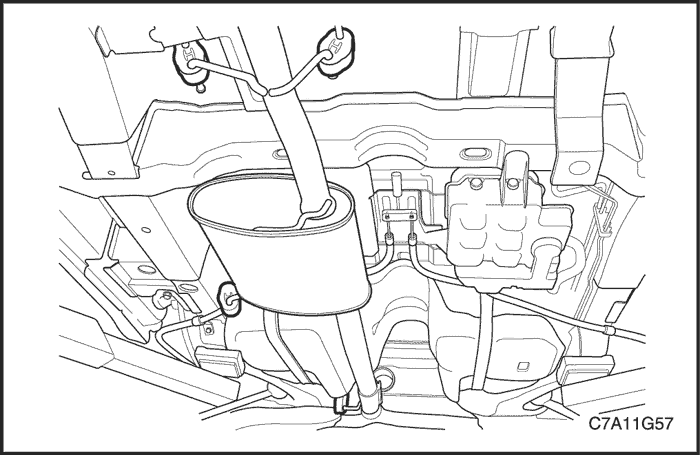
Fuel Tank
Removal Procedure
Caution : Do not allow smoking or the use of open flames in the area where work on the fuel system is taking place. Anytime work is being done on the fuel system, disconnect the negative battery cable, except for those tests where battery voltage is required.
- Disconnect the negative battery cable.
- Drain the fuel tank. Ensure that the fuel level in the tank is less than1/4 full. If necessary, drain the fuel tank to at least this level.
- Raise and support the vehicle.
- Remove the front muffler. Refer to Section 1G1, Engine Exhaust – 2.0 Diesel.
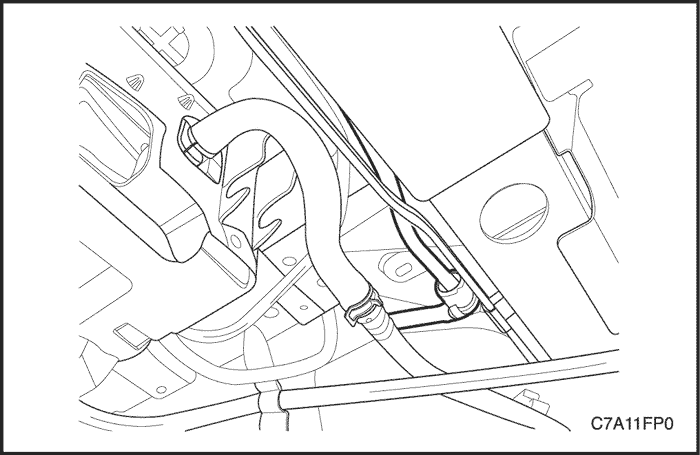
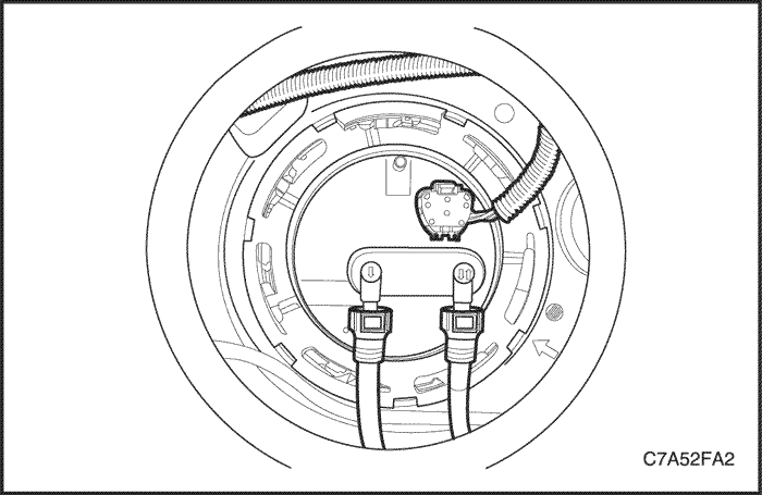
- Disconnect the fuel pump connector at the right rear side of the fuel tank.
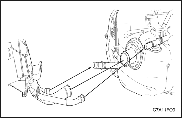
- Disconnect the fuel tank filler tube from the fuel tank.
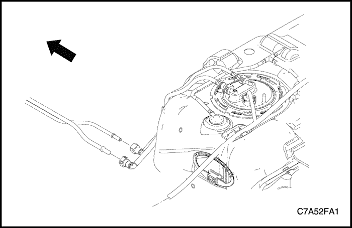
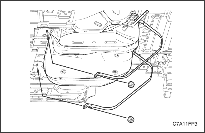
- Disconnect the fuel feed and return line near the right front side of the fuel tank.
- Remove the rear drive axle, if equipped. Refer to Section3B, Rear Drive Axle.
- Support the fuel tank.
- Remove the fuel tank strap retaining nuts.
- Remove the fuel tank straps.
- Carefully lower the jack and move the front of the fuel pump downward while tilting the rear of the fuel pump upward.
- Remove the fuel tank.
Installation Procedure
- Install the fuel tank in the position previously removed.
- Install the fuel tank straps.
Tighten
Tighten the fuel tank strap retaining nuts to 20 N•m (15 lb-ft).
- Connect the fuel feed and return line near the right front side of the fuel tank.
- Connect the fuel tank filler tube.
- Connect the fuel pump connector at the right rear side of the fuel tank.
Fuel Pump Assembly
Tools Required
EN–48279 Main Fuel Pump Locking Ring Remover/Installer
EN–48278 Sub Fuel Pump Locking Ring Remover/Installer
Removal Procedure
- Disconnect the negative battery cable.
- Fold the rear seat.
- Lift up the carpet and the insulation.
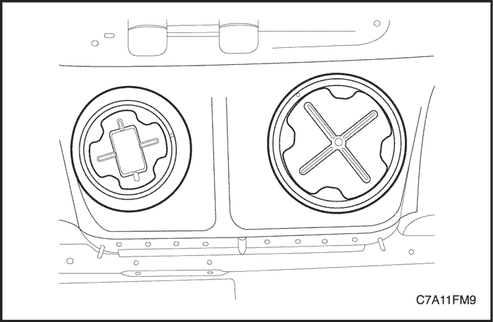
- Remove the main and sub fuel pump access covers.
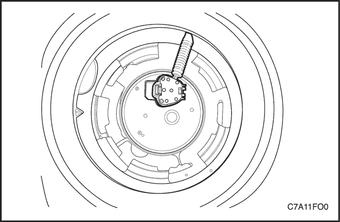
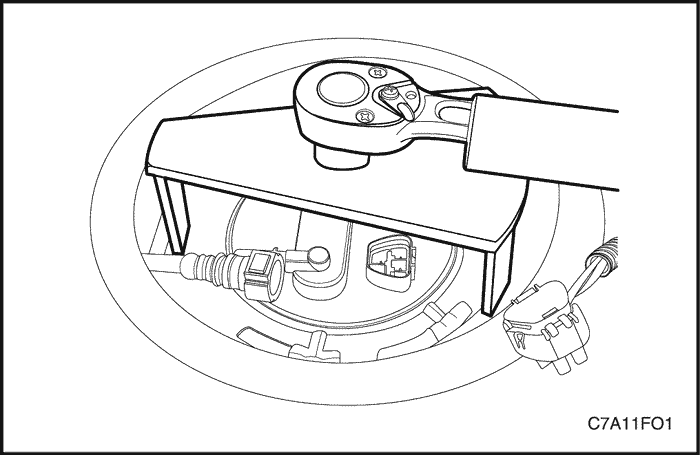
- Disconnect the electrical connector at the sub fuel pump assembly.
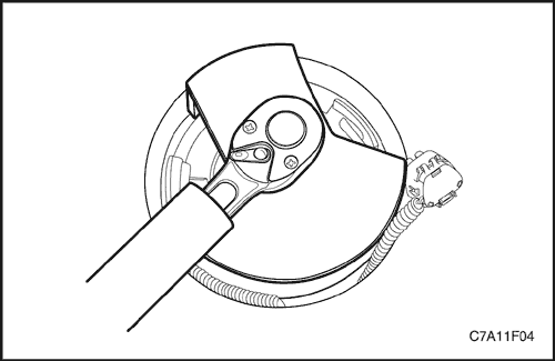
- Install the sub fuel pump lock ring remover/installer EN–48278 to the sub fuel pump and turn it counterclockwise.
- Remove the sub fuel pump lock ring.
Notice : Be careful not to damage the fuel sender for the correct fuel leveling while removing the fuel pump assembly from the fuel tank.
- Remove the sub fuel pump assembly and the O–ring from the fuel tank.
Notice : O–ring should not be contaminated by fuel.
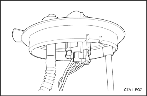
- Disconnect the main fuel pump–to–sub fuel pump connecting hose at the sub fuel pump.
- Disconnect the electrical connector at the main fuel pump assembly.
- Disconnect the fuel feed and return line.
- Install the main fuel pump lock ring remover/installer EN–48279 to the main fuel pump and turn it counterclockwise.
- Remove the main fuel pump lock ring.
Notice : Be careful not to damage the fuel sender for the correct fuel leveling while removing the fuel pump assembly from the fuel tank.
- Remove the main fuel pump assembly and the O–ring from the fuel tank.
Notice : O–ring should not be contaminated by fuel.
Installation Procedure
- Clean all of the mating surface on the both fuel pump and fuel tank.
Notice : For ease of the main fuel pump–to–sub fuel pump connecting hose, install the main fuel pump assembly first.
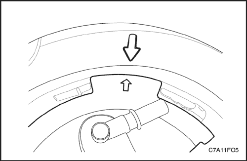
Notice : Be sure that the arrow on the main fuel pump assembly should be aligned with the arrow on the fuel tank.
Notice : Be careful not to damage the fuel sender for the correct fuel leveling while installing the fuel pump assembly to the fuel tank.
Caution : Do not reuse the main fuel pump O–ring.
- Position the new main fuel pump O–ring and the main fuel pump first into the fuel tank in the same location as removed.
- Pull the main fuel pump–to–sub fuel pump connecting hose towards the sub fuel pump assembly.
- Connect the main fuel pump–to–sub fuel pump connecting hose at the sub fuel pump.
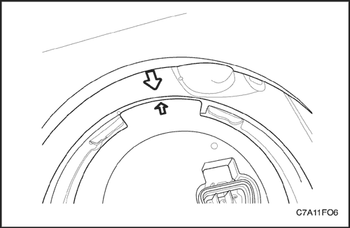
Notice : Be sure that the arrow on the sub fuel pump assembly should be aligned with the arrow on the fuel tank.
Notice : Be careful not to damage the fuel sender for the correct fuel leveling while installing the fuel pump assembly to the fuel tank.
Caution : Do not reuse the sub fuel pump O–ring.
- Position the new sub fuel pump O–ring and the sub fuel pump into the fuel tank in the same location as removed.
- Install the sub fuel pump lock ring by turning the sub fuel pump lock ring remover/installer EN–48278 clockwise.
- Connect the electrical connector at the sub fuel pump.
- Install the main fuel pump lock ring by turning the main fuel pump lock ring remover/installer EN–48279 clockwise.
- Connect the electrical connector at the main fuel pump.
- Connect the fuel feed and return line.
- Install the main and sub fuel pump access covers.
- Connect the negative battery cable.
- Perform an operational check of the fuel pump.
- Fold the rear seat back to the original position.
Fuel Sender
Replacement Procedure
Notice : The illustrations in this section show the fuel sender on the main fuel pump ONLY. The fuel sender on the sub fuel pump is similar.
Notice : Be careful not to damage the fuel sender for the correct fuel leveling while removing or installing the fuel pump assembly from the fuel tank.
- Remove the fuel pump assembly. Refer to "Fuel Pump Assembly" in this section.
- Disconnect the fuel sender connector.
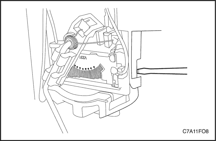
- Press the locking tap by using a suitable tool such as a screwdriver.
- Remove the fuel sender assembly by sliding it out from the fuel pump.
Notice : Improper installation of the fuel sender on the fuel pump may cause the incorrect fuel leveling.
- Install the fuel sender in the reverse order of removal.
- Install the fuel pump assembly into the fuel tank. Refer to "Fuel Pump Assembly" in this section.
Fuel Filter/Water in Fuel Sensor/Fuel Heater and Temperature Sensor
Tools Required
EN–48303 Fuel Filter Housing Holder
EN–48304 Fuel Filter Locker Installer/Remover
Removal Procedure
Caution : Do not allow smoking or the use of open flames in the area where work on the fuel system is taking place. Anytime work is being done on the fuel system, disconnect the negative battery cable, except for those tests where battery voltage is required.
- Disconnect the negative battery cable.
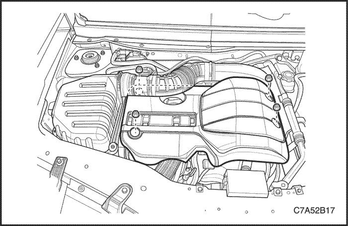
- Remove the beauty cover. Refer to Section 1B, Engine Mechanical-2.0 Diesel.
- Remove the air cleaner assembly. Refer to Section 1B, Engine Mechanical-2.0 Diesel.
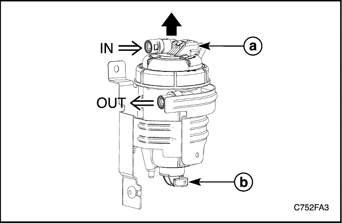
- Disconnect the fuel inlet/outlet line from the fuel filter.
- Disconnect the fuel heater and temperature sensor connector.(a)
- Disconnect the water in fuel sensor connector.(b)
- Remove the fuel filter assembly from the bracket upward.
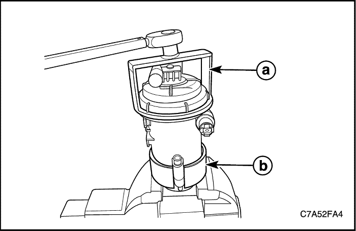
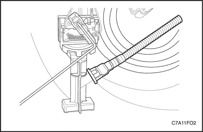
- Install the filter housing holder EN-48303(a) and the fuel filter locker installer/remover EN-48304(b) to the fuel filter assembly.
- Turn the fuel filter locker installer/remover EN-48304(b) counterclockwise.
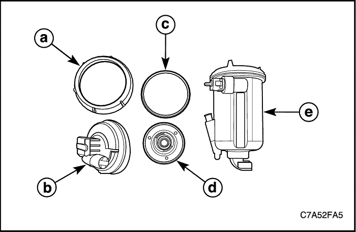
- Remove the fuel filter locker(a).
- Remove the fuel filter cap(b) with the O-ring(c).
- Remove the fuel filter(d) in the fuel filter housing(e).
Notice : The fuel filter cap includes the fuel heater and temperature sensor as one body. Also, the fuel filter housing includes the water in fuel sensor as one body.
Caution : It is impossible to reuse the fuel filter element if exposed the element to the air over a minute.
Water Draining Procedure
- Turn the water-in-fuel drain screw counterclockwise.
- If finished, unscrew the drain screw reverse toward.
- Do work fuel priming. Refer to “Fuel Priming” in this Section.
Installation Procedure
Caution : Do not touch the fuel filter element by hands. Damaged fuel element has influence on the engine performance and damage to the injection pump and injectors.
- Install the fuel filter(d) into the fuel filter housing(e).
- Install the fuel filter cap(b) with a new O-ring(c).
- Install the fuel filter locker(a) using by the filter housing holder EN-48303 and the fuel filter locker installer/remover EN-48304.
Tighten
Tighten the fuel filter locker to 30 N•m (22.1 lb-ft).
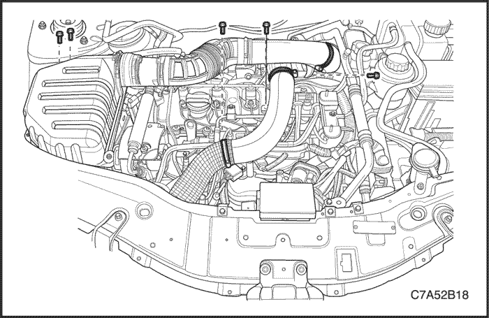
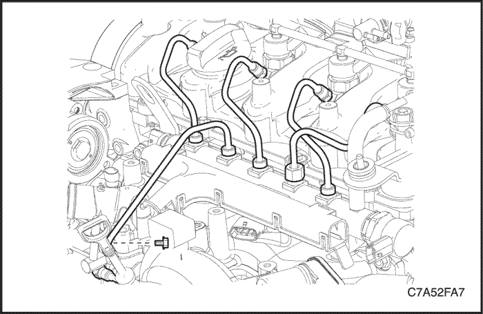
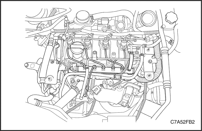
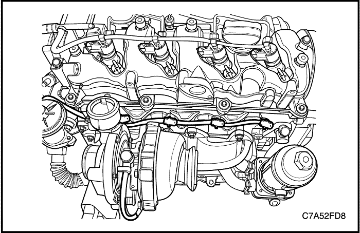
High Pressure Fuel Feeding Pipes
Removal Procedure
Caution : Do not allow smoking or the use of open flames in the area where work on the fuel system is taking place. Anytime work is being done on the fuel system, disconnect the negative battery cable, except for those tests where battery voltage is required.
- Remove the beauty cover. Refer to Section 1B, Engine Mechanical-2.0 Diesel.
- Remove the charge air system. Refer to Section 1B, Engine Mechanical-2.0 Diesel.
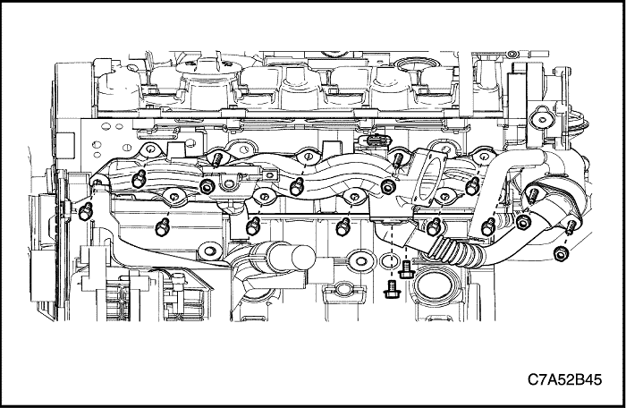
- Hold the injector pipe connector(a) and unscrew the fuel pipe-to-injector nut(M14).
Caution : To avoid fuel spillage or damage from the injector pipe connector, hold the injector pipe connector using by tools and unscrew the pipe nut. And then, put a cap on the injector connector to avoid contamination from dust as soon as the fuel pipes are removed. A little dust may be clogged the injectors.
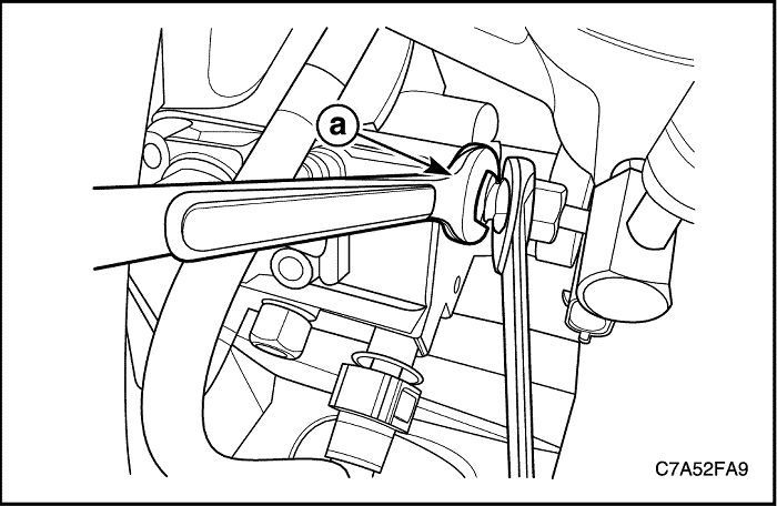
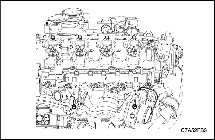
- Hold the injection pump pipe connector(a) and unscrew the fuel pipe-to-common rail nut(M14).
Caution : To avoid fuel spillage or damage from the injection pump pipe connector, hold the injection pump pipe connector using by tools and unscrew the fuel pipe-to-common rail nut(M14). And then, put a cap on the injection pipe connector to avoid contamination from dust as soon as the fuel pipes are removed. A little dust may be clogged the injectors.
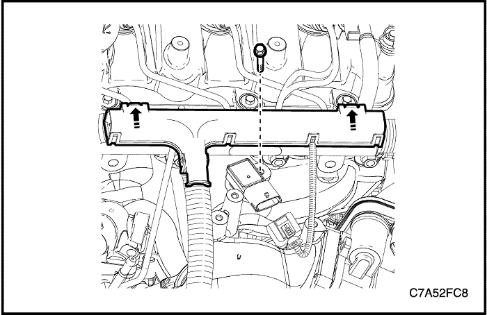
- Unscrew the fuel pipe-to-common rail nut(M17).
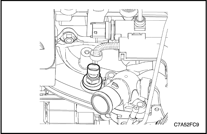
- Remove the fuel pipe-to-common rail retaining bolt from the thermostat housing.
- Remove the fuel pipe-to-common rail and the fuel pipe-to-injector pipes.
Caution : Put a cap on the common rail pipes thread to avoid contamination from dust as soon as the threads are removed. A little dusts may be clogged the injectors.
Installation Procedure
Important : It is impossible to reuse the fuel pipes. If reused, the contaminated pipes may be damaged the injectors or leaked from the pipes.
Caution : It is impossible to reuse the fuel pipes. If reused, the contaminated pipes may be damaged the injectors or leaked from the pipes.
Caution : Do not wipe clean a towel onto the pipes connectors of the injectors, the injection pump and the common rail pipe threads. If contaminated, wipe clean an oilpaper on the dust area.
- Clean the common rail pipe thread using by oilpaper, if contaminated.
- Loose the injector bracket bolts. Refer to "Injector" in this Section.
- Install the fuel pipes and tighten the nuts manually between the injectors and the common rail.
Caution : Do not tighten the fuel pipe nuts by tool.
- Tighten the injector bracket bolts.
Tighten
Tighten the injector bracket bolt to 28 N•m (20.7 lb-ft).
- Hold the injector pipe connector(a) and tighten the fuel pipe-to-injector nut(M14).
Tighten
Tighten the fuel pipe-to-injector nut(M14) to 27 N•m (19.9 lb-ft).
- Tighten the fuel pipe-to-injector nut(M17).
Tighten
Tighten the fuel pipe-to-injector nut(M17) to 20 N•m (14.8 lb-ft).
- Install the fuel pipe and tighten the nuts manually between the common rail and the injection pump.
Caution : Do not tighten the fuel pipe nuts by tool.
- Hold the injection pump pipe connector(a) and tighten the fuel pipe-to-common rail nut(M14).
Tighten
Tighten the fuel pipe-to-common rail nut(M14) to 20 N•m (14.8 lb-ft).
- Tighten the fuel pipe-to-common rail nut(M17).
Tighten
Tighten the fuel pipe-to-common rail nut(M17) to 20 N•m (14.8 lb-ft).
Fuel Injection Pump
Removal Procedure
Caution : Do not allow smoking or the use of open flames in the area where work on the fuel system is taking place. Anytime work is being done on the fuel system, disconnect the negative battery cable, except for those tests where battery voltage is required.
- Remove the high pressure fuel pipes. Refer to “High Pressure Fuel Feeding Pipes” in this Section.
- Remove the intake manifold. Refer to Section 1B, Engine Mechanical-2.0 Diesel.
- Remove the timing belt. Refer to Section 1B, Engine Mechanical-2.0 Diesel.
- Remove the power steering pump. Refer to Section 6B, Power Steering Pump.
Caution : Put a cap on the injection pump pipe connector to avoid contamination from dust as soon as the fuel pipes are removed. A little dust may be clogged the injectors.
- Remove the injection pump sprocket with the woodruff key.
- Remove the injection pump assembly.
Installation Procedure
Important : It is impossible to reuse the fuel pipes. If reused, the contaminated pipes may be damaged the injectors or leaked from the pipes.
Caution : Do not blow air using by air gun onto pipes connectors of the injectors, the injection pump and the common rail pipe threads. If contaminated, wipe clean an oilpaper on the dust area.
Caution : Do not wipe clean a towel onto the pipes connectors of the injectors, the injection pump and the common rail pipe threads. If contaminated, wipe clean an oilpaper on the dust area.
- Install the injection pump assembly.
Tighten
Tighten the injection pump bolts to 30 N•m (22.1 lb-ft).
- Put the woodruff key groove of the injection pump drive shaft.
- Install the injection pump sprocket.
- Install the injection pump sprocket nut manually.
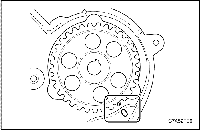
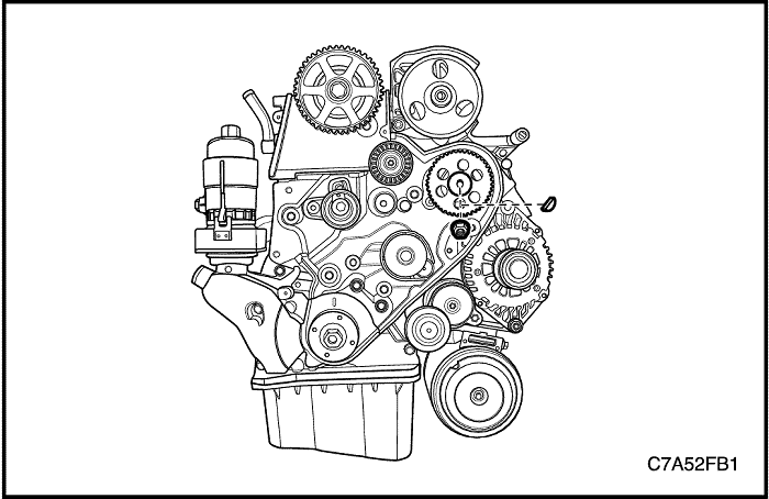
- Align the sprocket mark on the timing belt rear cover mark.
- Install and align the timing belt. Refer to Section 1B, Engine Mechanical-2.0 Diesel.
- Install the injection pump sprocket nut.
Tighten
Tighten the injection pump sprocket nut to 70 N•m (51.6 lb-ft).
- Do work the fuel priming. Refer to “Fuel Priming” in this Section.
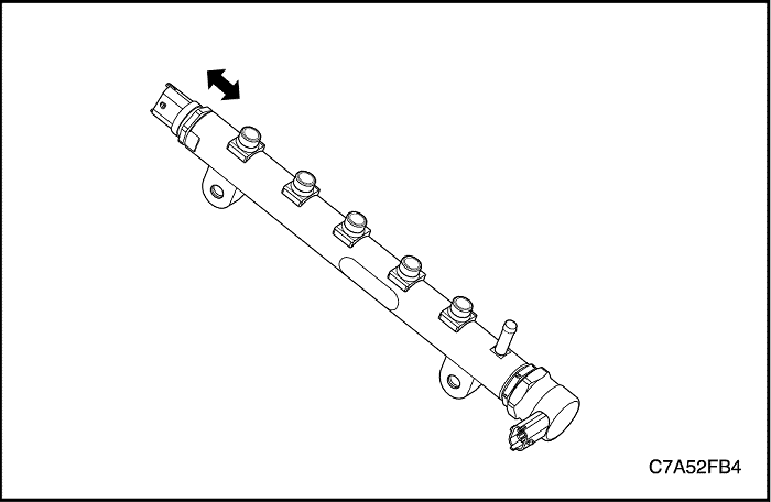
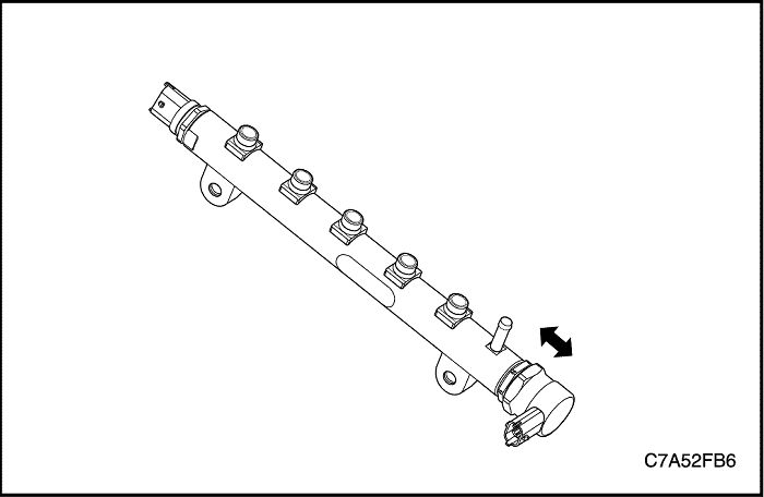
Fuel Common Rail
Caution : Do not allow smoking or the use of open flames in the area where work on the fuel system is taking place. Anytime work is being done on the fuel system, disconnect the negative battery cable, except for those tests where battery voltage is required.
Removal Procedure
- Disconnect the negative battery cable.
- Disconnect the common rail pressure sensor connector.
- Disconnect the common rail regulator connector.
- Disconnect the common rail return hose.
- Remove the engine wiring guide from the intake manifold.
- Remove the high pressure fuel pipes. Refer to “High Pressure Fuel Feeding Pipes” in this Section.
- Remove the common rail assembly.
Caution : Put a cap on the common rail pipe threads to avoid contamination from dust as soon as the fuel pipes are removed. A little dust may be clogged the injectors.
Installation Procedure
Important : It is impossible to reuse the fuel pipes. If reused, the contaminated pipes may be damaged the injectors or leaked from the pipes.
Caution : Do not blow air using by air gun onto pipes connectors of the injectors, the injection pump and the common rail pipe threads. If contaminated, wipe clean an oilpaper on the dust area.
Caution : Do not wipe clean a towel onto the pipes connectors of the injectors, the injection pump and the common rail pipe threads. If contaminated, wipe clean an oilpaper on the dust area.
- Install the common rail assembly.
Tighten
Tighten the common rail retaining bolts to 25 N•m (18.4 lb-in).
- Install the fuel pipes to the common rail. Refer to “High Pressure Fuel Feeding Pipes” in this Section.
- Connect the common rail pressure sensor connector.
- Connect the common rail regulator connector.
- Do work the fuel priming. Refer to “Fuel Priming” in this Section.
Common Rail Pressure Sensor
Caution : Do not allow smoking or the use of open flames in the area where work on the fuel system is taking place. Anytime work is being done on the fuel system, disconnect the negative battery cable, except for those tests where battery voltage is required.
Removal Procedure
- Remove the common rail assembly. Refer to “Fuel Common Rail” in this Section.
- Clean interface area of the rail pressure sensor using proper degreases materials and compressed air for drying.
Notice : Cleaning material must not penetrate the electric connector.
- Remove the rail pressure sensor with the gasket if equipped.
Caution : Put a cap on the common rail pressure sensor to avoid contamination from dust as soon as the fuel pipes are removed. A little dust may be clogged the injectors.
Installation Procedure
Caution : Do not blow air using by air gun onto pipes connectors of the injectors, the common rail and the injection pump. If contaminated, wipe clean an oilpaper on the dust area.
Caution : Do not wipe clean a towel onto the pipes connectors of the injectors, the common rail and the injection pump. If contaminated, wipe clean an oilpaper on the dust area.
- Inspect and clean the thread and the sealing surface of the rail.
- Inspect and clean thread of the rail pressure sensor.
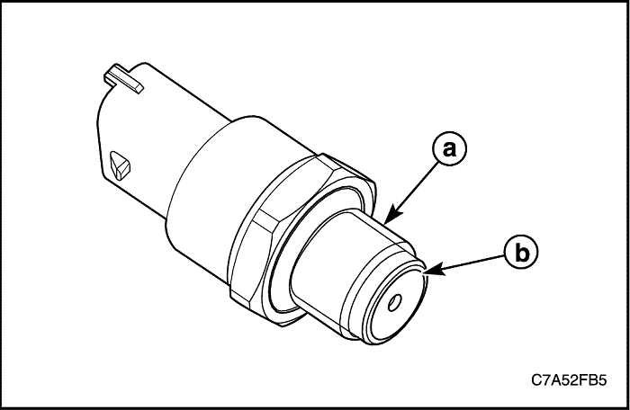
- Lubricate thread(a) and bite edge(b) of the rail pressure sensor using lubricant Ft1v27 (Only apply a thin lubrication film).
- Install the rail pressure sensor to the common rail.
Tighten
Tighten the rail pressure sensor to 70 N•m (51.6 lb-ft).
- Do work the fuel priming. Refer to “Fuel Priming” in this Section.
- If you replace the new one, reset the Zero Fuel Comection (ZFC) EEPRM values by scan tool.
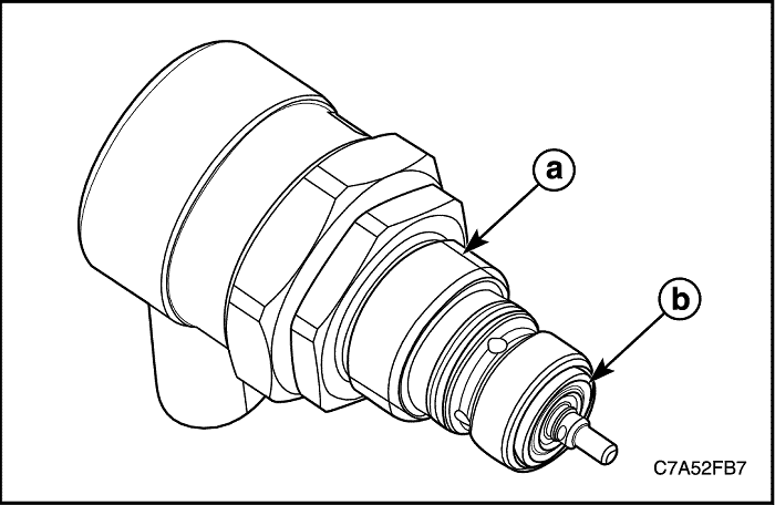
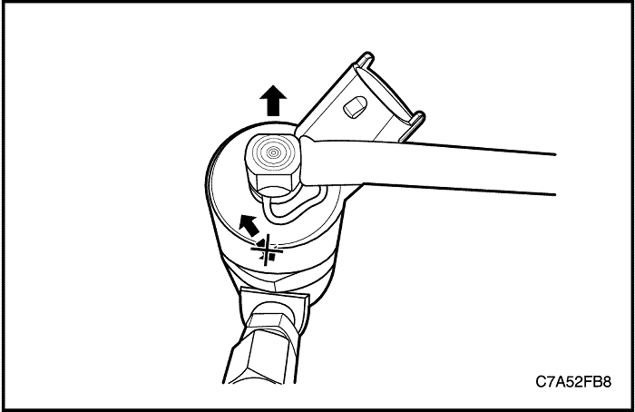
Common Rail Regulator
Caution : Do not allow smoking or the use of open flames in the area where work on the fuel system is taking place. Anytime work is being done on the fuel system, disconnect the negative battery cable, except for those tests where battery voltage is required.
Removal Procedure
- Remove the common rail assembly. Refer to “Fuel Common Rail” in this Section.
- Clean interface area of the rail regulator using proper degreases materials and compressed air for drying.
Notice : Cleaning material must not penetrate the electric connector.
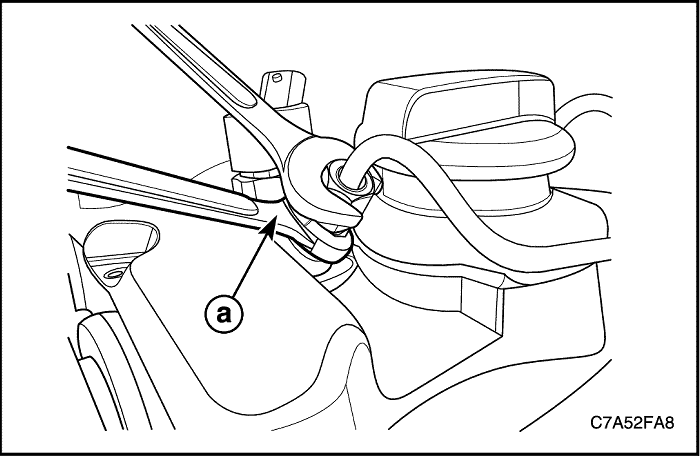
- Loosen the component using a commercial wrench WAF30 grasp it by hand and pull it out simultaneously turning it counter-clockwise.
Installation Procedure
Important : This common rail regulator and O-ring must not be reused.
Caution : Do not blow air using by air gun onto pipes connectors of the injectors, the injection pump and the common rail pipe threads. If contaminated, wipe clean an oilpaper on the dust area.
Caution : Do not wipe clean a towel onto the pipes connectors of the injectors, the injection pump and the common rail pipe threads. If contaminated, wipe clean an oilpaper on the dust area.
- Inspect and clean the thread and the sealing surface of the rail.
- Inspect and clean thread(a) and bite edge(b) of the common rail regulator.
Notice : Inspect sealing surfaces of the DRV and the rail or the high pressure pump. Only concentric grooves are allowed. No cuts in radial direction are tolerable. Inspect the Torx screws or the flange screw concerning any damages.
- Lubricate the O-rings with fuel.
- Install the common rail regulator using a commercial wrench WAF30 counteracting with a wrench WAF35 at the hexagon of the housing.
Tighten
Tighten the common rail regulator to 60 N•m (44.3 lb-ft) and turn the regulator 90 degrees in the opposite direction and 85 N•m (62.7 lb-ft).
- Do work the fuel priming. Refer to “Fuel Priming” in this Section.
Fuel Return Line Assembly
Caution : Do not allow smoking or the use of open flames in the area where work on the fuel system is taking place. Anytime work is being done on the fuel system, disconnect the negative battery cable, except for those tests where battery voltage is required.
Removal Procedure
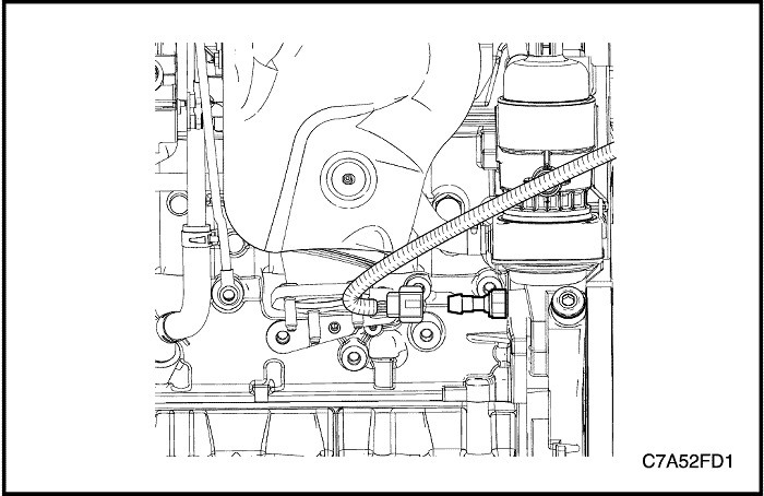
- Remove the injector return hose.
Important : Do not pull the clip out but push it and simultaneously disconnect the injector return hoses. If removed from the injector, it is impossible to reuse the clip.
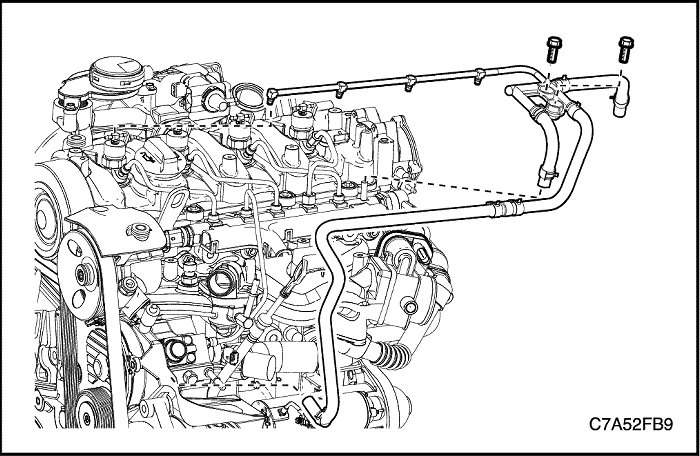
- Disconnect the injection pump return hose.
- Disconnect the common rail return hose.
- Remove the junction block retaining bolts.
- Remove the fuel return line assembly.
Installation Procedure
- Install the fuel return line assembly.
- Connect the common rail return hose.
Important : Press injector return line by hand from above and vertically down to the injector until you hear the connection piece snaps in place.
- Connect the injection pump return hose.
- Install the junction block.
Tighten
Tighten the junction block retaining bolts to 11 N•m (97.4 lb-in).
Injector
Tools Required
EN-48357 Injector Remover
Caution : Do not allow smoking or the use of open flames in the area where work on the fuel system is taking place. Anytime work is being done on the fuel system, disconnect the negative battery cable, except for those tests where battery voltage is required.
Removal Procedure
- Disconnect the negative battery cable.
- Remove the high pressure fuel pipes. Refer to “High Pressure Fuel Feeding Pipes” in this Section.
- Remove the injector return hoses. Refer to “Fuel Return Line Assembly” in this Section.
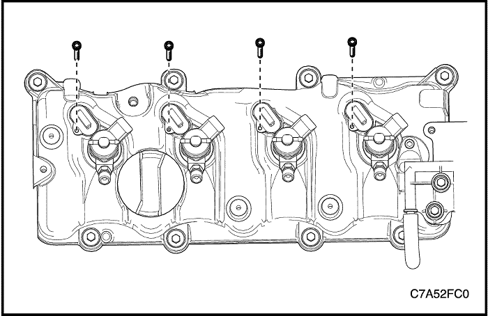
- Disconnect the injector connector.
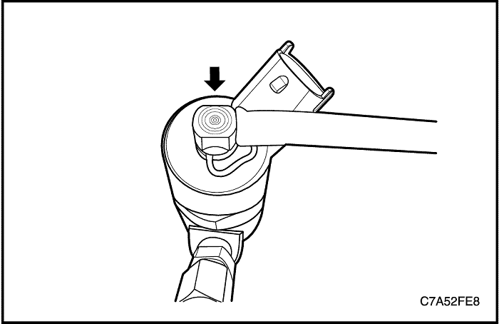
- Remove the injector bracket plug.
- Unscrew the injector bracket bolt.
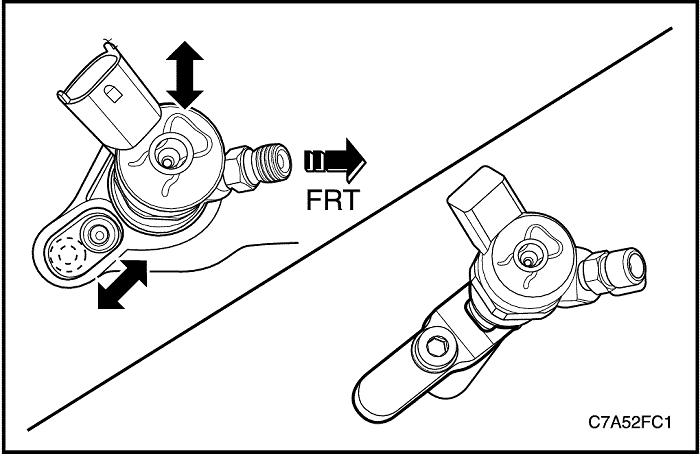
- Pull the injector bracket out from the injector using by the bolt manually.
- Remove the injectors with the washer upward.
Caution : Numbering the injectors using a pen in sequence. If mixed up with the injector number, it has influence on the engine performance.
Caution : Secure the injector nozzle tip against ground or rigid area. If possible, put a cap to the nozzle tip.
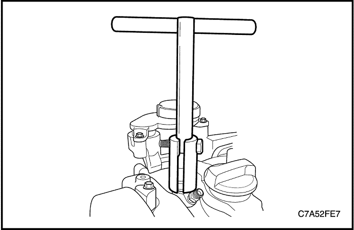
- If the injectors stick to the cylinder head, use the injector remover EN-48357.
Installation Procedure
Caution : The injector washer must not be reused.
- Inspect and clean the injectors and nozzle tip.
Caution : Do not wipe clean the nozzle tip area. It may be damaged the nozzle hole.
- Install the injector with a new washer.
- Insert the injector bracket into the injector groove.
- Tighten the injector bracket bolt.
Tighten
Tighten the injector bracket bolt to 28 N•m (20.7 lb-ft).
- Install the injector bracket plug.
Tighten
Tighten the injector bracket plug bolt to 7 N•m (62.0 lb-in).
Important : It is impossible to reuse the fuel pipes. If reused, the contaminated pipes may be damaged the injectors or leaked from the pipes.
- Do work the fuel priming. Refer to “Fuel Priming” in this Section.
Important : If replaced the new injector or exchanged injector sequences, reprogram and reset zero fuel correction (ZFC) EEPRM values the injectors using by scan tool.
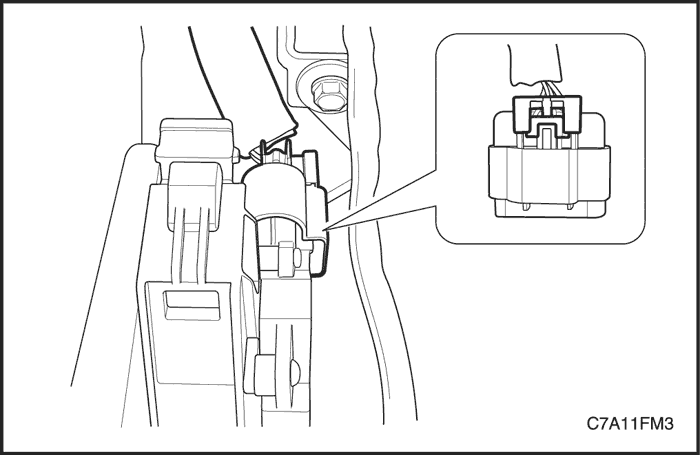
Accelerator Pedal Module (APM)
Removal Procedure
- Disconnect the negative battery cable.
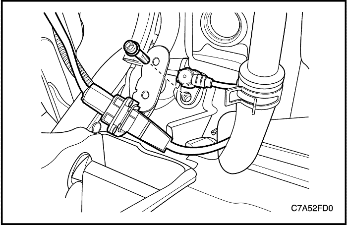
- Disconnect the accelerator pedal module (APM) connector locking tab from the APM connector.
- Disconnect the APM connector.
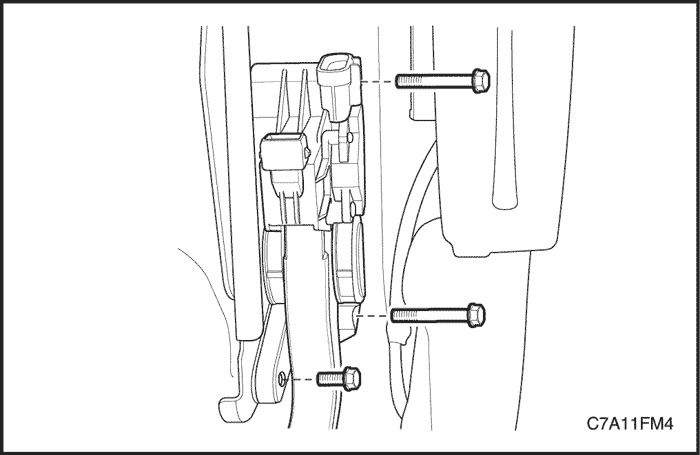
- Remove the bolts, three places, attaching the APM from the accelerator and brake pedal module bracket.
Installation Procedure
- Install the APM retaining bolts to the accelerator and brake pedal module bracket.
Tighten
Tighten the accelerator pedal module retaining bolts to 9 N•m (80 lb-in).
- Connect the APM connector and the install the locking tab firmly.
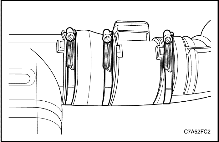
Mass Air Flow Sensor(MAF)
Removal/Installation Procedure
- Disconnect the negative battery cable.
- Disconnect the MAF sensor connector.
- Remove the MAF sensor.
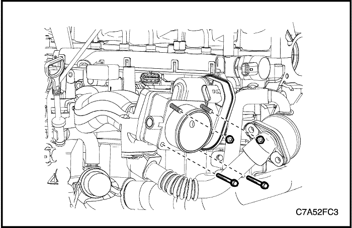
Electric Throttle Control(ETC)
Removal/Installation Procedure
- Disconnect the negative battery cable.
- Remove the beauty cover. Refer to Section 1B, Engine Mechanical-2.0 Diesel.
- Remove the charge air cooler outlet hose. Refer to Section 1B, Engine Mechanical-2.0 Diesel.
- Disconnect the remove ETC connector.
- Remove the ETC.
Tighten
Tighten the ETC retaining bolts and nuts to 9 N•m (79.7 lb-in).
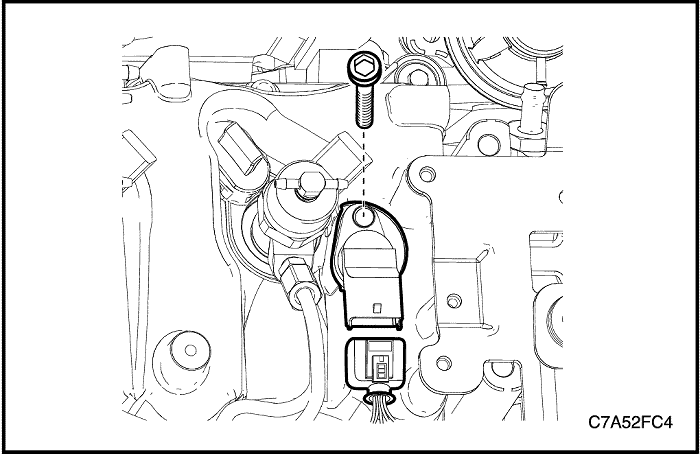
Camshaft Position Sensor(CMP)
Removal/Installation Procedure
- Remove Disconnect the negative battery cable.
- Remove the beauty cover. Refer to Section 1B, Engine Mechanical-2.0 Diesel.
- Remove the junction block bolt. Refer to “Fuel Return Line Assembly” in this Section.
- Disconnect the CMK sensor connector.
- Remove the CMK sensor.
Tighten
Tighten the CMK sensor retaining bolt to 7 N•m (62 lb-in).
Vacuum Pump
Removal Procedure
- Remove Disconnect the negative battery cable.
- Remove the beauty cover. Refer to Section 1B, Engine Mechanical-2.0 Diesel.
- Remove the junction block bolts. Refer to “Fuel Return Line Assembly” in this Section.
- Remove the beauty cover bracket.
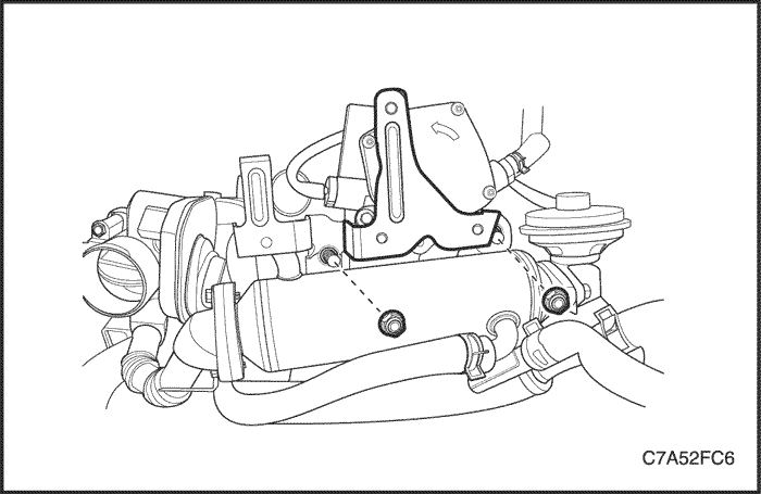
- Remove the engine wiring harness bracket.
- Disconnect the EGR and brake booster vacuum hoses.
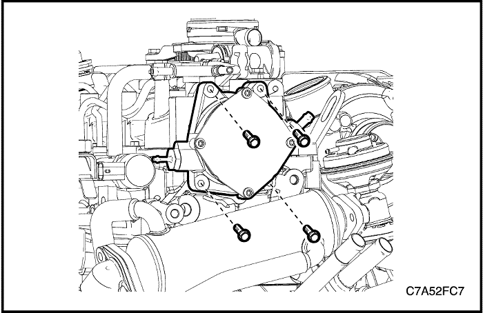
- Remove the vacuum pump.
Installation Procedure
- Install the vacuum pump.
Tighten
Tighten the vacuum pump tightening bolts to 12 N•m (8.9 lb-ft).
- Install the engine wiring harness bracket.
- Connect the EGR and brake booster vacuum hoses.
Tighten
Tighten the engine wiring harness bracket nuts to 20 N•m (14.8 lb-ft).
- Install the beauty cover bracket.
Tighten
Tighten the beauty cover bracket bolts to 11 N•m (97.4 lb-in).
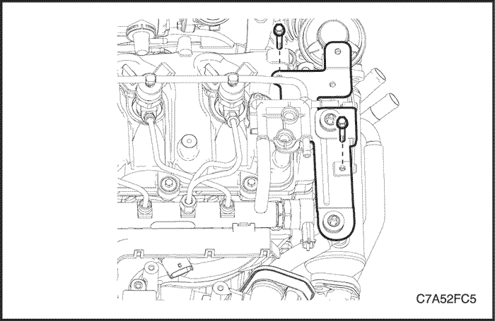
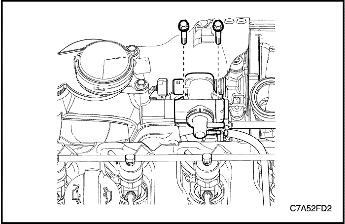
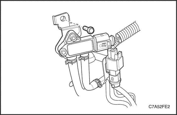
Boost Pressure Sensor(T-MAP Sensor)
Removal/Installation Procedure
- Disconnect the negative battery cable.
- Remove beauty cover. Refer to Section 1B, Engine Mechanical-2.0 Diesel.
- Disconnect the boost pressure sensor connector.
- Remove the engine wiring harness cover upward.
- Remove the boost pressure sensor.
Tighten
Tighten the boost pressure sensor bolt to 8 N•m (70.8 lb-in).
Engine Coolant Temperature(ECT) Sensor
Removal/Installation Procedure
- Disconnect the negative battery cable.
- Remove beauty cover. Refer to Section 1B, Engine Mechanical-2.0 Diesel.
- Disconnect the ECT sensor connector.
- Remove the ECT sensor.
Tighten
Tighten the ECT sensor to 35 N•m (25.8 lb-ft).
Crankshaft Position(CKP) Sensor
Removal/Installation Procedure
- Disconnect the negative battery cable.
- Disconnect the CKP sensor connector.
- Remove the CKP sensor.
Tighten
Tighten the CKP sensor retaining bolt to 7 N•m (62 lb-in).
Oil Pressure Switch
Removal/Installation Procedure
- Disconnect the negative battery cable.
- Drain the engine oil.
- Disconnect the oil pressure switch connector.
- Remove the oil pressure switch.
Tighten
Tighten the oil pressure switch to 30 N•m (22.1 lb-ft).
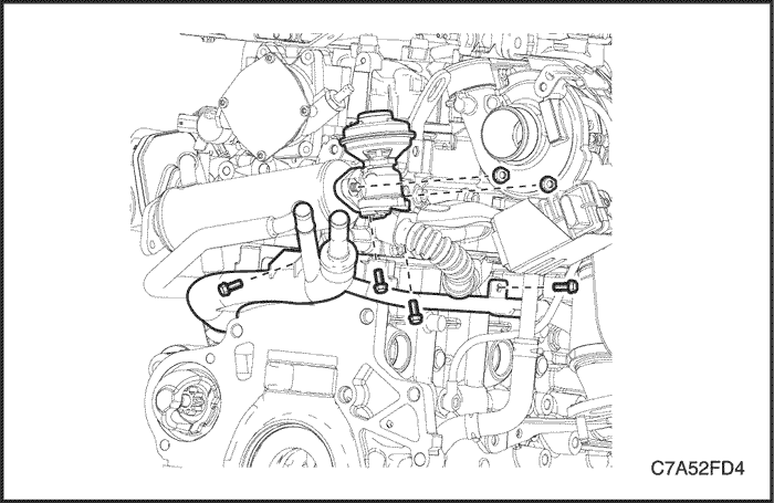
EGR Vacuum Solenoid Valve
Removal/Installation Procedure
- Disconnect the negative battery cable.
- Remove beauty cover. Refer to Section 1B, Engine Mechanical-2.0 Diesel.
- Disconnect the EGR vacuum solenoid valve inlet/outlet hoses.
- Disconnect the EGR vacuum solenoid valve connector.
- Remove the EGR vacuum solenoid valve.
Tighten
Tighten the EGR vacuum solenoid valve retaining bolts to 7 N•m (62 lb-in).
EGR System
Removal/Installation Procedure
Caution : Make sure to confirm that the components are cool. And do work.
- Disconnect the negative battery cable.
- Remove beauty cover. Refer to Section 1B, Engine Mechanical-2.0 Diesel.
- Remove the charge air system hoses and ducts. Refer to Section 1B, Engine Mechanical-2.0 Diesel.
- Drain the engine coolant. Refer to Section 1D1, Engine Cooling-2.0 Diesel.
- Remove the battery and tray. Refer to Section 1E1, Engine Electrical-2.0 Diesel.
- Remove the ECM. Refer to “ECM” in this Section.
- Remove the beauty cover bracket. Refer to “Vacuum Pump” in this Section.
- Remove the engine wiring harness bracket. Refer to “Vacuum Pump” in this Section.
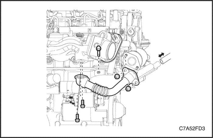
- Remove the EGR cooler outlet pipe.
- Disconnect the surge tank-to-water pipe hose.
- Disconnect the heater-to-water pipe hose.
- Remove the water pipe retaining bolt from the engine block on the front.
- Remove the EGR valve.
- Remove the water pipe retaining bolts from the engine block on the rear and side.
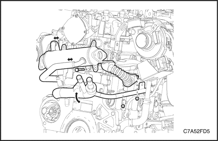
- Lower the water pipe.
- Remove the EGR cooler.
- Remove the EGR cooler inlet pipe from the exhaust manifold.
Installation Procedure
- Install the EGR cooler inlet pipe to the exhaust manifold.
- Install the EGR cooler with the engine wiring harness bracket.
Tighten
- Tighten the EGR cooler inlet pipe retaining nuts to 33 N•m (24.3 lb-ft).
- Tighten the EGR cooler retaining bolt to 20 N•m (14.8 lb-ft).
- Install the EGR valve.
- Install the water pipe retaining bolt onto the engine block.
Tighten
- Tighten the EGR valve retaining nuts(to EGR cooler) to 20 N•m (14.8 lb-ft).
- Tighten the EGR valve retaining bolts(to EGR inlet pipe) to 20 N•m (14.8 lb-ft).
- Tighten the water pipe retaining bolt(M6) to 9 N•m (79.7 lb-in).
- Tighten the water pipe retaining bolt(M8) to 20 N•m (14.8 lb-in).
- Install the EGR cooler outlet pipe.
- Install the water pipe retaining bolt onto the engine block on the front.
Tighten
- Tighten the EGR cooler outlet pipe retaining bolts and nuts to 20 N•m (14.8 lb-ft).
- Tighten the water pipe retaining bolt(M8) to 20 N•m (14.8 lb-in).
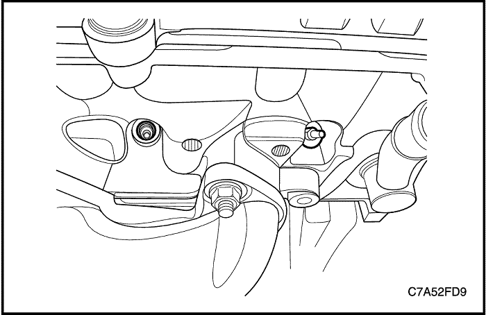
Turbocharger
Removal/Installation Procedure
Caution : Make sure to confirm that the components are cool. And do work.
- Disconnect the negative battery cable.
- Remove beauty cover. Refer to Section 1B, Engine Mechanical-2.0 Diesel.
- Remove the charge air system hoses and ducts. Refer to Section 1B, Engine Mechanical-2.0 Diesel.
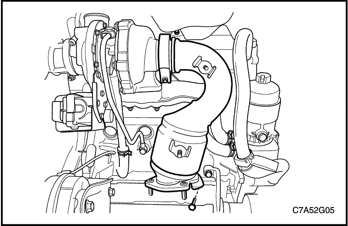
- Remove the PCV valve and adapter. Refer to Section 1B, Engine Mechanical-2.0 Diesel.
- Remove the pre-catalyst converter. Refer to Section 1G1, Engine Exhaust-2.0 Diesel.
- Disconnect the turbocharger actuator connector.
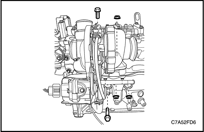
- Remove the turbocharger wheel bearing oil inlet pipe.
- Disconnect the turbocharger wheel bearing oil out hose.
- Remove the turbocharger.
Installation Procedure
- Install the turbocharger to the exhaust manifold.
- Install the turbocharger wheel bearing oil inlet pipe.
- Connect the turbocharger wheel bearing oil out hose.
Tighten
- Tighten the turbocharger tightening nuts to 34 N•m (25.1 lb-ft).
- Tighten the turbocharger wheel bearing oil inlet pipe bolts to 23 N•m (17 lb-ft).
Glow Plug
Removal/Installation Procedure
Caution : Make sure to confirm that the components are cool. And do work.
- Disconnect the negative battery cable.
- Remove beauty cover. Refer to Section 1B, Engine Mechanical-2.0 Diesel.
- Remove the charge air system hoses and ducts. Refer to Section 1B, Engine Mechanical-2.0 Diesel.
- Remove the PCV valve and adapter. Refer to Section 1B, Engine Mechanical-2.0 Diesel.
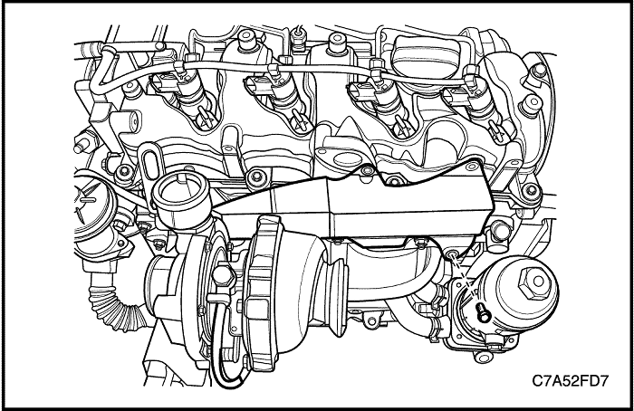
- Remove the glow plug heat shield.
- Disconnect the glow plug wiring harness.
- Remove the glow plug.
Notice : If needed to remove the No.3 and No. 4 glow plugs, remove the turbocharger before.
Installation Procedure
- Install the glow plug.
Tighten
Tighten the glow plug to 9 N•m (79.7 lb-in).
- Install the glow plug heat shield.
Tighten
- Tighten the glow plug heat shield bolt to 20 N•m (14.8 lb-ft).
- Tighten the glow plug heat shield nut(engine lift bracket retaining nut) to 28 N•m (20.6 lb-ft).
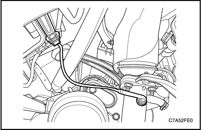
Exhaust Gas Temperature(EGT) Sensor 1
Removal/Installation Procedure
- Disconnect the negative battery cable.
- Disconnect the EGT sensor 1 connector.
- Remove the EGT sensor 1 from the front exhaust pipe.
Tighten
Tighten the EGT sensor 1 to 45 N•m (33.2 lb-ft).
Exhaust Gas Temperature(EGT) Sensor 2
Removal/Installation Procedure
- Disconnect the negative battery cable.
- Disconnect the EGT sensor 2 connector.
- Remove the EGT sensor 2 from the DPF.
Tighten
Tighten the EGT sensor 2 to 45 N•m (33.2 lb-ft).
DPF Pressure Sensor
Removal/Installation Procedure
- Remove the air cleaner assembly. Refer to Section 1B, Engine Mechanical-2.0 Diesel.
- Disconnect the negative battery cable.
- Disconnect the DPF pressure hoses.
- Disconnect the DPF pressure sensor connector.
- Remove the DPF pressure sensor bracket bolt.
Tighten
Tighten the DPF pressure sensor bracket bolt to 10 N•m (88.5 lb-in).
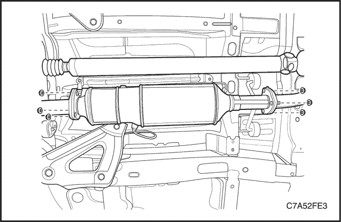
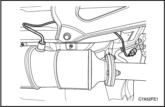
Diesel Particulate Filter(DPF)
Removal/Installation Procedure
- Disconnect the negative battery cable.
- Disconnect the EGT sensor 2 connector.
- Disconnect the DPF pressure hoses.
- Remove the DPF assembly.
Tighten
Tighten the DPF retaining nuts to 30 N•m (22.1 lb-ft).
- If you replace the DPF new one, reset DPF EEPROM values using by scan tool.
Regeneration Procedure
Caution : While the DPF regeneration, exhaust system is very hot temperature. To avoid a fire or damage, lift the vehicle using by lifter and make a unapproachable state around the exhaust system.
- Warning up the engine.
- Do regenerate the DPF using by scan tool.
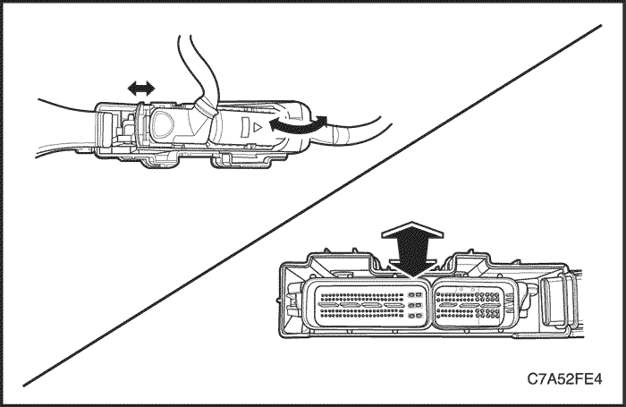
ECM and Bracket
Removal Procedure
- Disconnect the negative battery cable.
- Remove the beauty cover. Refer to Section 1B, Engine Mechanical-2.0 Diesel.
- Disconnect the ECM connectors.
- Press the ECM retaining clip between the ECM and bracket using by common plate driver and simultaneously extract the ECM from the bracket upward.
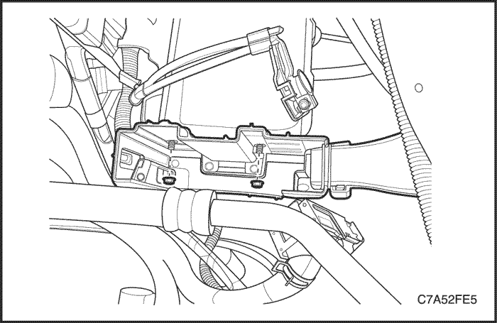
- Remove the ECM bracket.
Installation Procedure
- Install the ECM bracket.
Tighten
Tighten the ECM bracket retaining nuts to 15 N•m (11.1 lb-ft).
- Install the ECM.
- Connect the ECM connectors.
Important : If replaced the new ECM, reprogram the ECM using by scan tool.
- Setup engine oil life
- Reset Zero Fuel Conection (ZFC) EEPROM values
- Reset DPF EEPROM values
| © Copyright Chevrolet Europe. All rights reserved |


