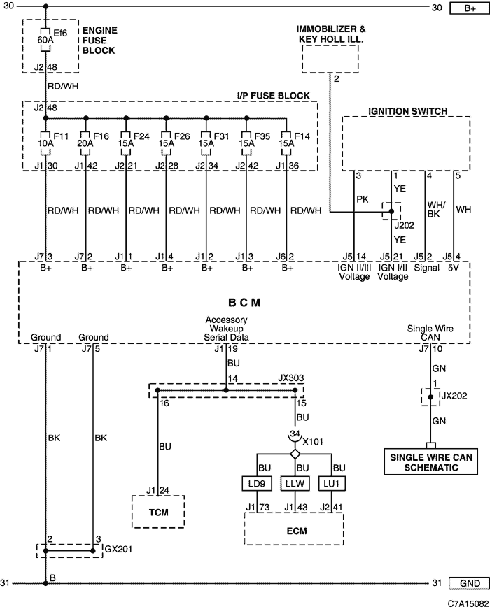
6. BCM (BODY CONTROL MODULE)
1) POWER SUPPLY, GROUND, IGNITION SWITCH CIRCUIT
a. CONNECTOR INFORMATION
CONNECTOR NO
(PIN NO, COLOR) | CONNECTING WIRING HARNESS | CONNECTOR POSITION |
| X101 (36 Pin, Black) | Engine - Body | Behind the Engine Fuse Block |
| X201 (92 Pin, Black) | Body - I.P | Below to the "A" pillar |
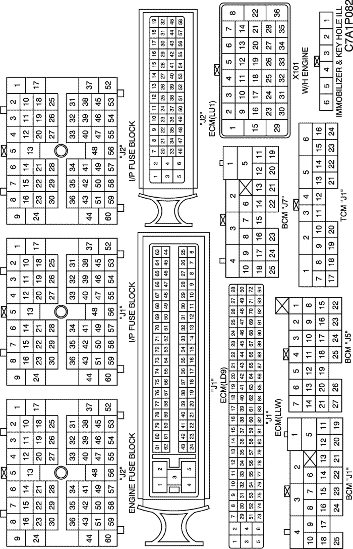
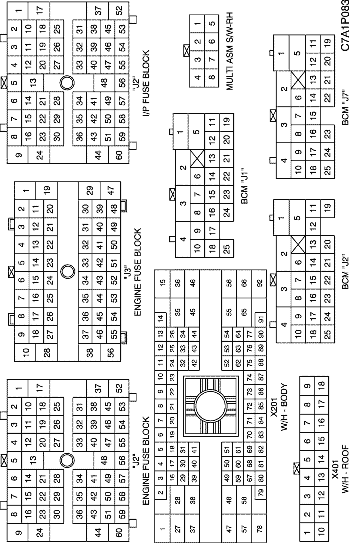
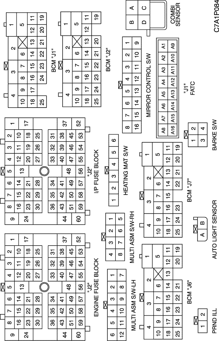
b. CONNECTOR IDENTIFICATION SYMBOL & PIN NUMBER POSITION
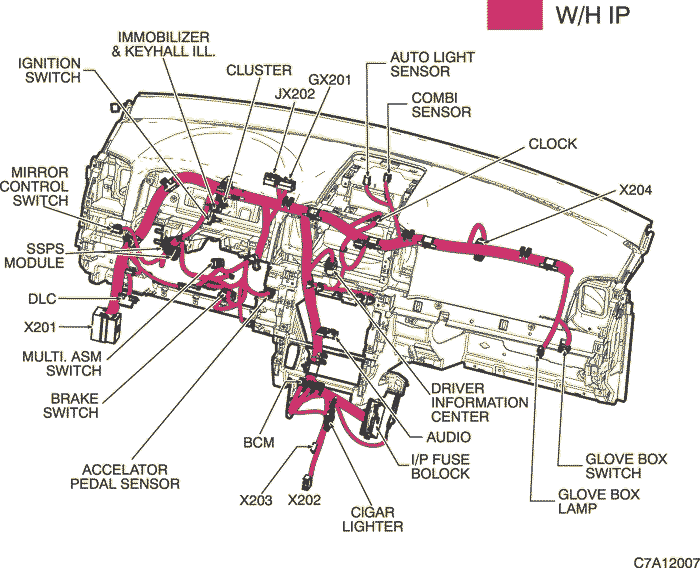
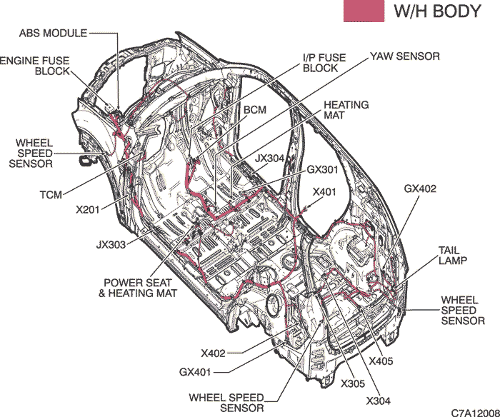
c. POSITION OF CONNECTORS AND GROUNDS
W/H INSTRUMENT PANEL
W/H BODY
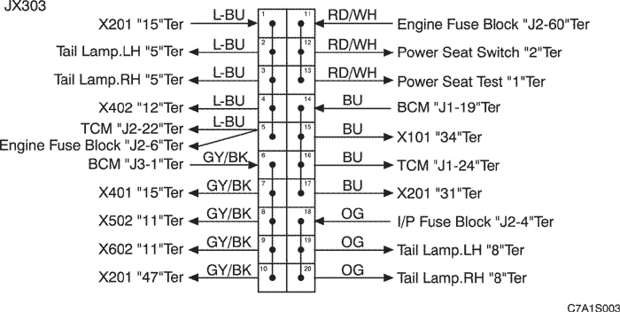
d. SPLICE PACK
JX303 (BLACK/BROWN)
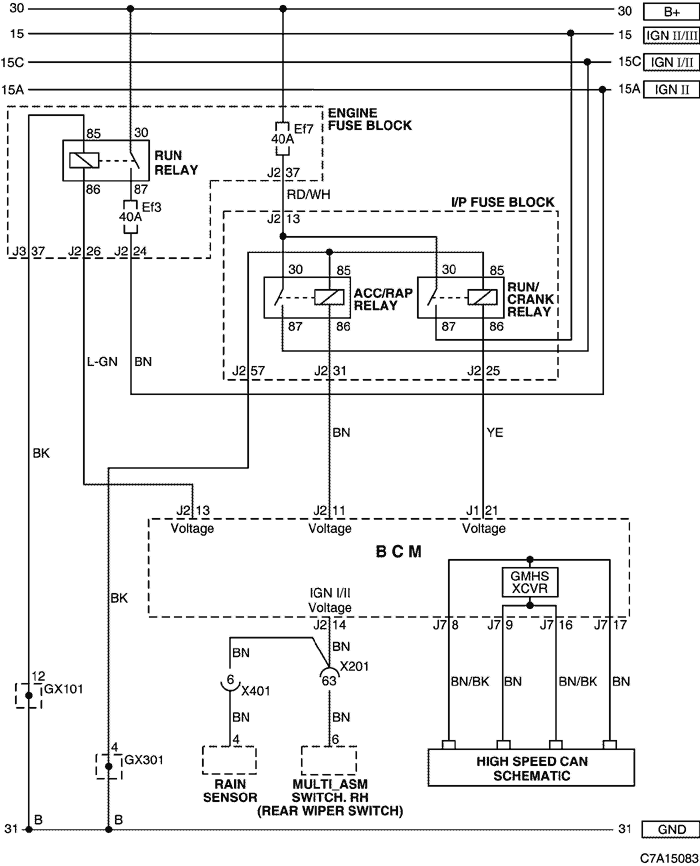
2) POWER MODE, RAIN SENSOR & REAR WIPER SWITCH CIRCUIT
a. CONNECTOR INFORMATION
CONNECTOR NO
(PIN NO, COLOR) | CONNECTING WIRING HARNESS | CONNECTOR POSITION |
| X201 (92 Pin, Black) | Body - I.P | Below to the "A" pillar |
| X401 (18 Pin, Colorless) | Roof - Body | Inside the left "C" pillar |
| GX101 (Black/Gray) | Front | Behind the left HeadLamp |
| GX301 (Black/Gray) | Body | Under the right seat cushion |
b. CONNECTOR IDENTIFICATION SYMBOL & PIN NUMBER POSITION
c. POSITION OF CONNECTORS AND GROUNDS
W/H BODY
W/H INSTRUMENT PANEL
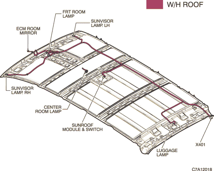
W/H ROOF
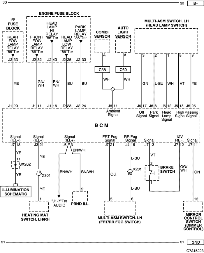
3) HEAD LAMP, ILLUMINATION, FRONT/REAR FOG, AUTO LIGHT SENSOR, BRAKE SWITCH & DIMMER CONTROL CIRCUIT
a. CONNECTOR INFORMATION
CONNECTOR NO
(PIN NO, COLOR) | CONNECTING WIRING HARNESS | CONNECTOR POSITION |
| X201 (92 Pin, Black) | Body - I.P | Below to the "A" pillar |
| X204 (16 Pin, Black) | I.P - FATC | Behind the FATC |
| X301 (12 Pin, Colorless) | Console - Body | Below the floor console |
b. CONNECTOR IDENTIFICATION SYMBOL & PIN NUMBER POSITION
c. POSITION OF CONNECTORS AND GROUNDS
W/H BODY
W/H INSTRUMENT PANEL
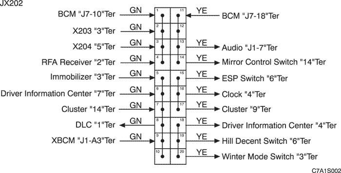
d. SPLICE PACK
JX202 (BLACK/PINK)
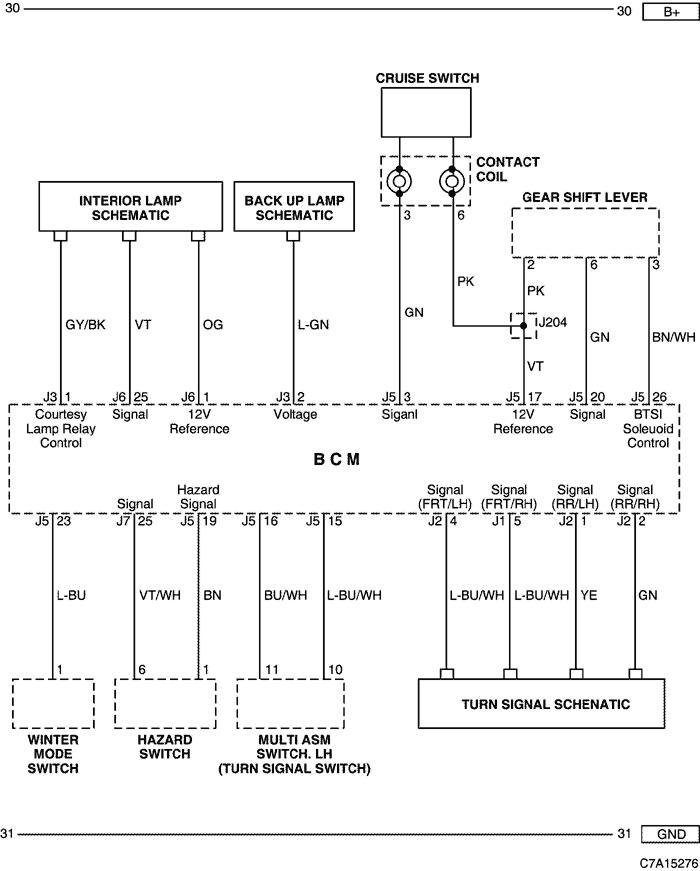
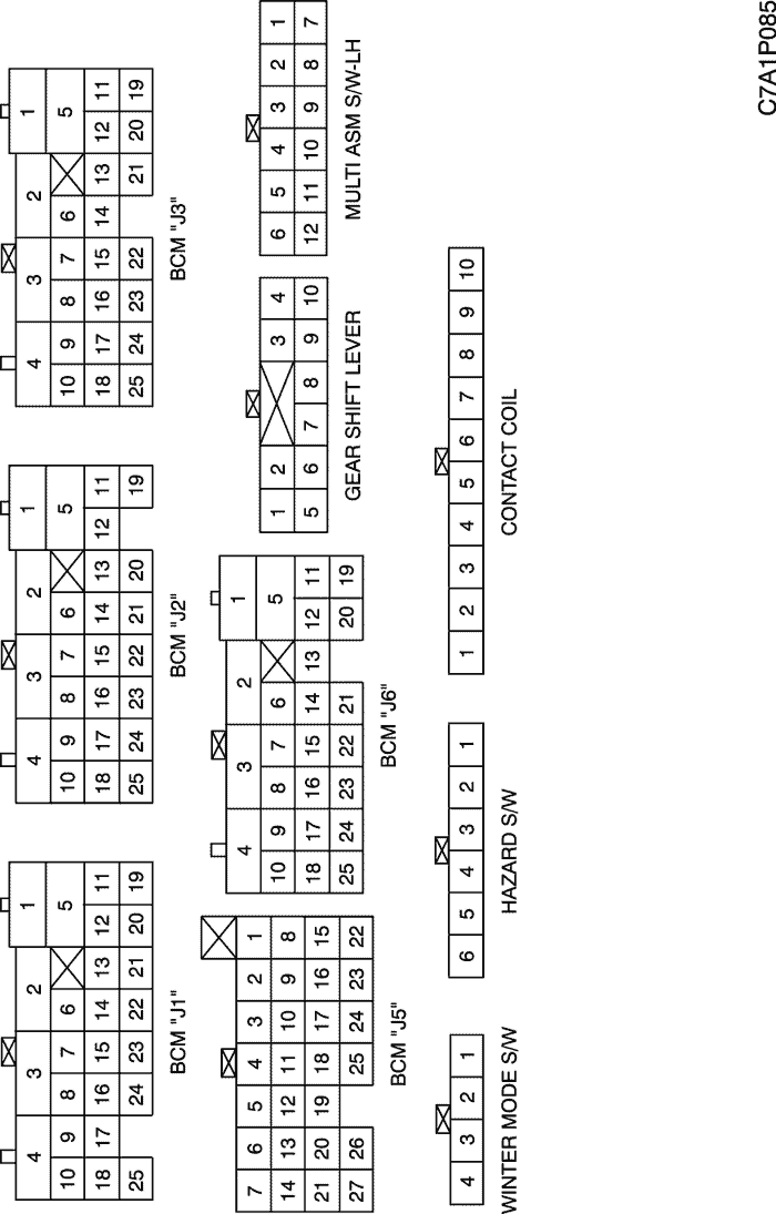
4) INTERIOR LAMP, BACK UP LAMP, GEAR SHIFT LEVEL, SWITCH(WINTER MODE, CRUISE, HAZARD, TURN SIGNAL) CIRCUIT
b. CONNECTOR IDENTIFICATION SYMBOL & PIN NUMBER POSITION
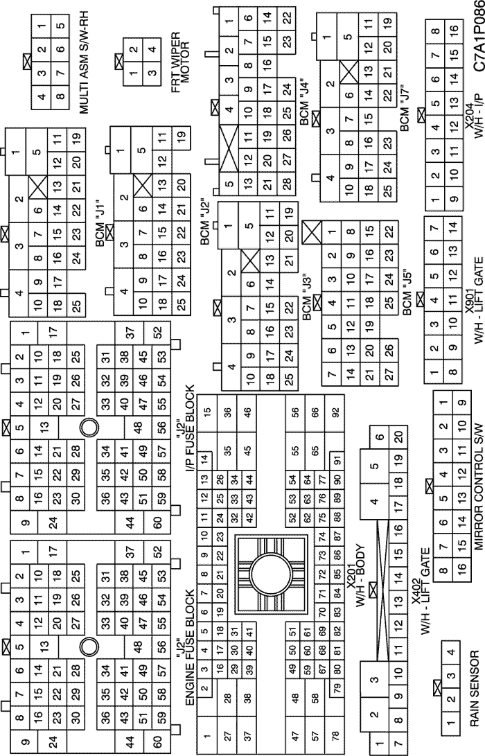
c. POSITION OF CONNECTORS AND GROUNDS
W/H INSTRUMENT PANEL
W/H BODY
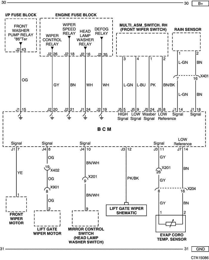
5) FRONT WIPER, LIFT GATE WIPER, RAIN SENSOR & EVAP CORE TEMP. SENSOR CIRCUIT
a. CONNECTOR INFORMATION
CONNECTOR NO
(PIN NO, COLOR) | CONNECTING WIRING HARNESS | CONNECTOR POSITION |
| X201 (92 Pin, Black) | Body - I.P | Below to the "A" pillar |
| X204 (16 Pin, Black) | I.P - FATC | Behind the FATC |
| X401 (18 Pin, Colorless) | Roof - Body | Inside the left "C" pillar |
| X402 (20 Pin, Colorless) | Lift Gate - Body | Behind the left "C" pillar |
| X901 (14 Pin, Colorless) | Lift Gate - Lift Gate JPR | Behind the "2nd" Seat |
b. CONNECTOR IDENTIFICATION SYMBOL & PIN NUMBER POSITION
c. POSITION OF CONNECTORS AND GROUNDS
W/H BODY
W/H ROOF
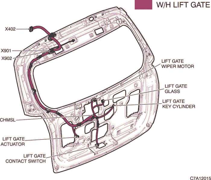
W/H LIFT GATE
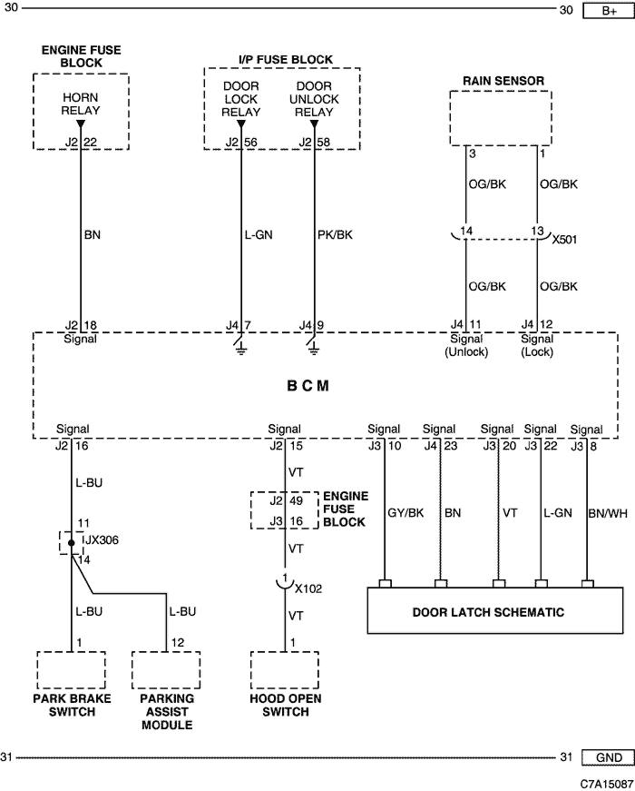
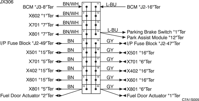
6) DOOR LOCK/UNLOCK, HORN, DOOR LATCH PARKING ASSIST & SWITCH (PARK BRAKE,HOOD OPEN) CIRCUIT
a. CONNECTOR INFORMATION
CONNECTOR NO
(PIN NO, COLOR) | CONNECTING WIRING HARNESS | CONNECTOR POSITION |
| X102 (12 Pin, Black) | Front JPR - Front | Behind the left side Head Lamp |
| X501 (18 Pin, Gray) | Body - Front LH Door | Under the left "A" Pillar |
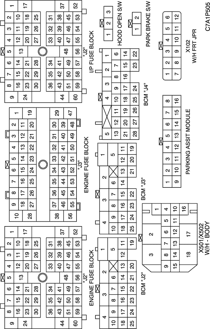
b. CONNECTOR IDENTIFICATION SYMBOL & PIN NUMBER POSITION
c. POSITION OF CONNECTORS AND GROUNDS
W/H BODY
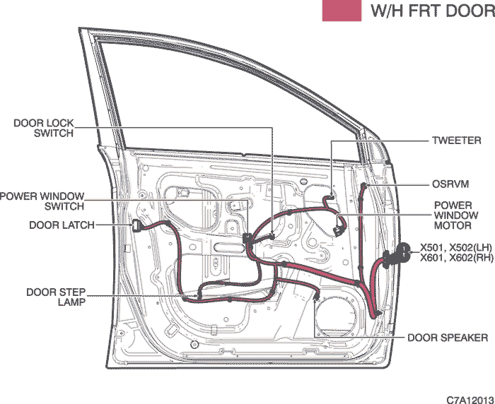
W/H FRONT DOOR
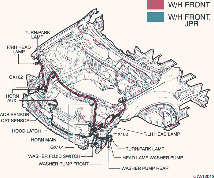
W/H FRONT
d. SPLICE PACK
JX306 (BLACK/BLUE)
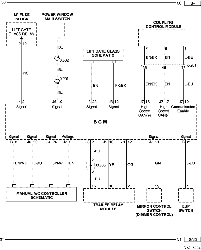
7) POWER WINDOW, LIFT GATE GLASS, AWD CONTROL MODULE, ESP SWITCH & MANUAL A/C CONTROLLER CIRCUIT
a. CONNECTOR INFORMATION
CONNECTOR NO
(PIN NO, COLOR) | CONNECTING WIRING HARNESS | CONNECTOR POSITION |
| X102 (12 Pin, Black) | Front JPR - Front | Behind the left side Head Lamp |
| X201 (92 Pin, Black) | Body - I.P | Below to the "A" pillar |
| X502 (18 Pin, Colorless) | Body - Front LH Door | Under the left "A" Pillar |
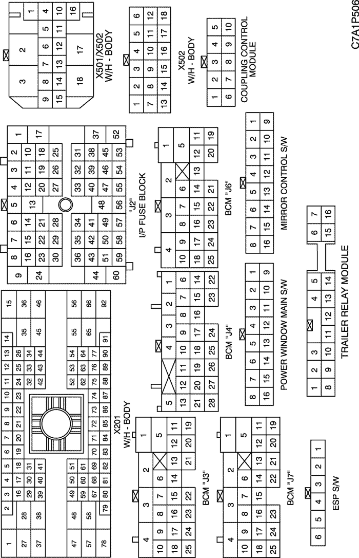
b. CONNECTOR IDENTIFICATION SYMBOL & PIN NUMBER POSITION
c. POSITION OF CONNECTORS AND GROUNDS
W/H INSTRUMENT PANEL
W/H BODY
W/H FRONT DOOR
| © Copyright Chevrolet Europe. All rights reserved |