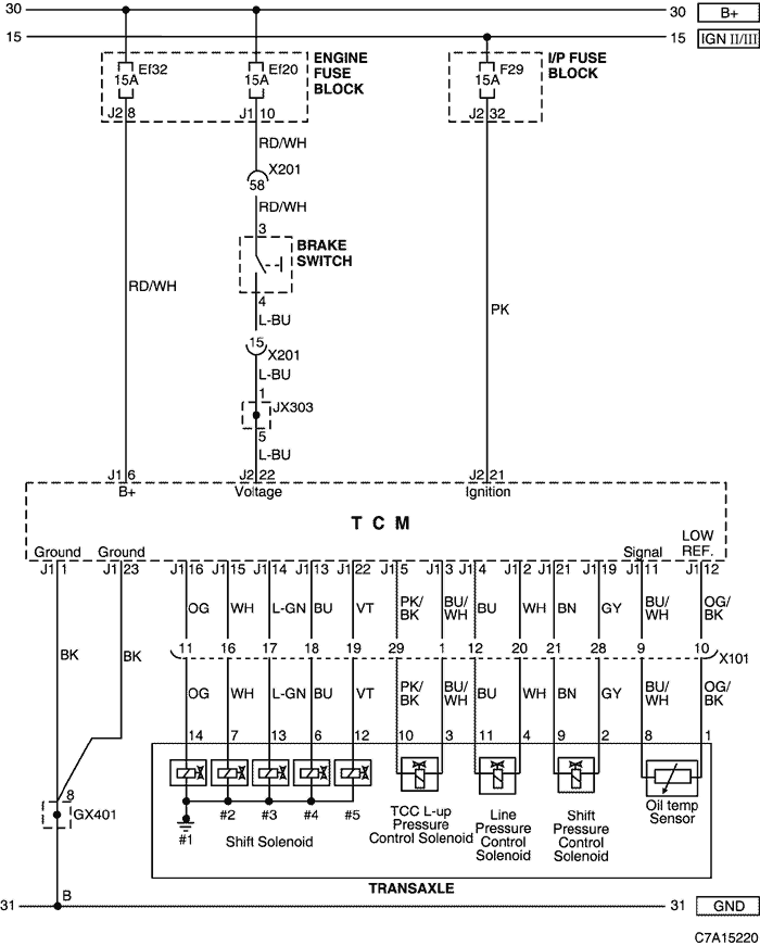
5. TCM (TRANSMISSION CONTROL MODULE)
1) POWER SUPPLY, GROUND, BRAKE SWITCH & SOLENOID VALVE CIRCUIT
a. CONNECTOR INFORMATION
CONNECTOR NO
(PIN NO, COLOR) | CONNECTING WIRING HARNESS | CONNECTOR POSITION |
| X101 (36 Pin, Black) | Engine - Body | Behind the Engine Fuse Block |
| X201 (92 Pin, Black) | Body - I.P | Below to the "A" pillar |
| GX401 (Black/Gray) | Body | Left the luggage compartment |
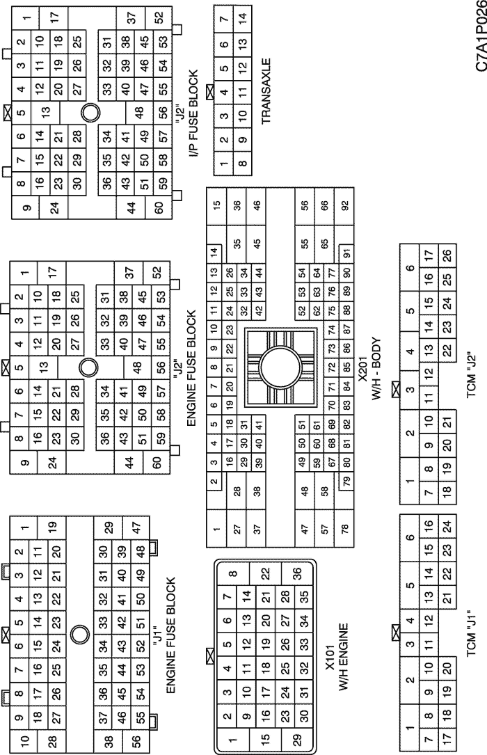
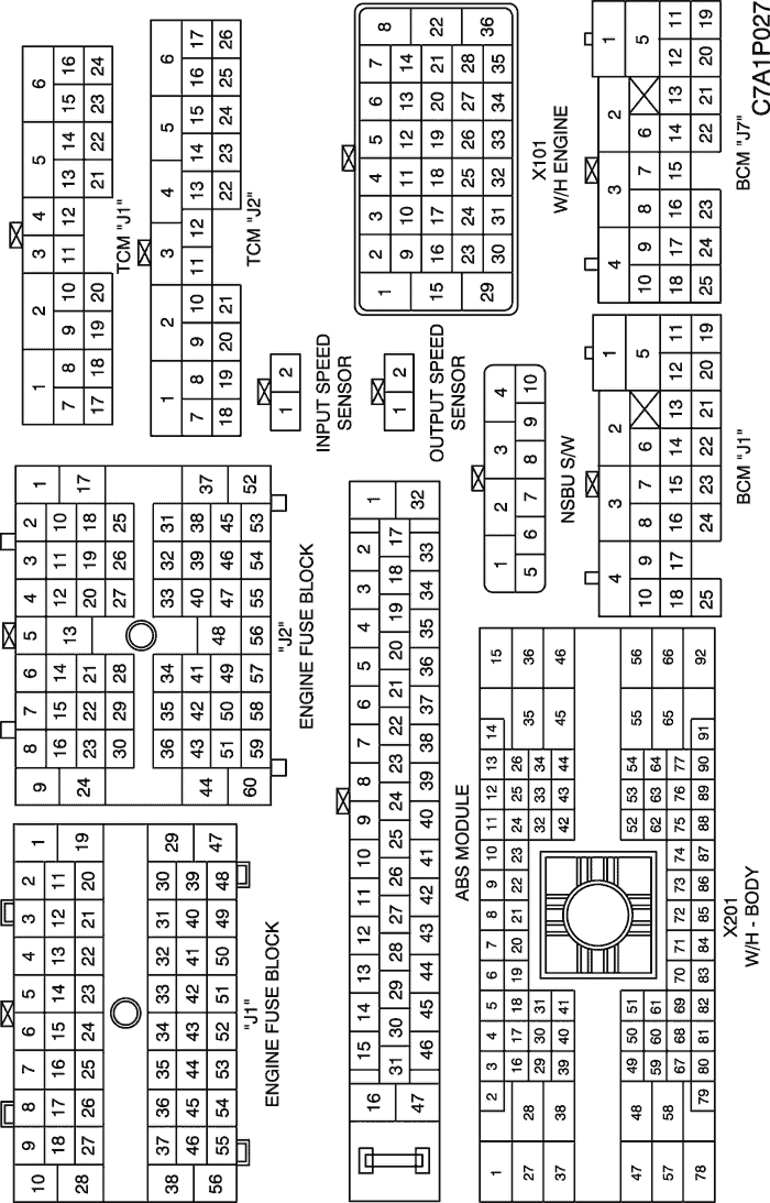
b. CONNECTOR IDENTIFICATION SYMBOL & PIN NUMBER POSITION
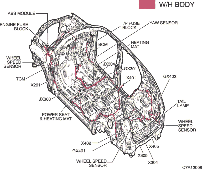
c. POSITION OF CONNECTORS AND GROUNDS
W/H BODY
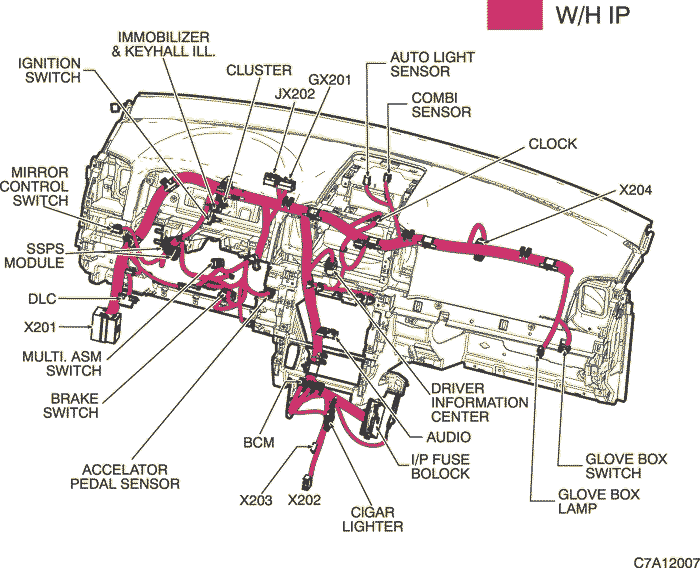
W/H INSTRUMENT PANEL
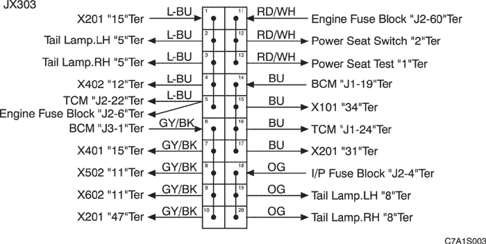
d. SPLICE PACK
JX303 (BLACK/BROWN)
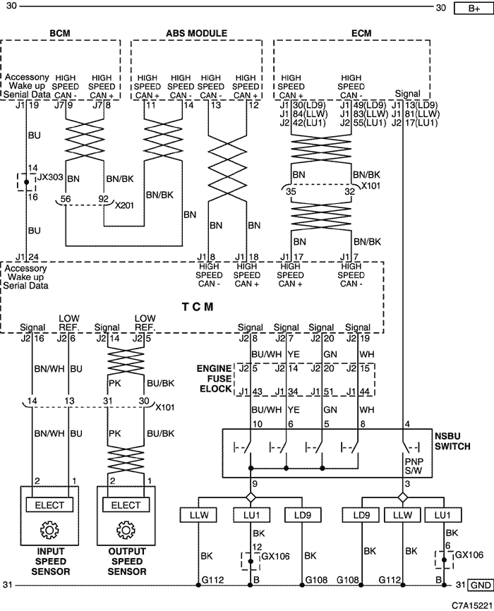
2) SENSOR (INPUT SPEED,OUTPUT SPEED), NSBU SWITCH & HIGH SPEED CAN CIRCUIT
a. CONNECTOR INFORMATION
CONNECTOR NO
(PIN NO, COLOR) | CONNECTING WIRING HARNESS | CONNECTOR POSITION |
| X101 (36 Pin, Black) | Engine - Body | Behind the Engine Fuse Block |
| X201 (92 Pin, Black) | Body - I.P | Below to the "A" pillar |
| GX106 (Black/Gray) | Engine (DSL/HFV6) | Upper the Cylinder Head |
| G108 | Engine (FAM II) | On the Cylinder Block |
b. CONNECTOR IDENTIFICATION SYMBOL & PIN NUMBER POSITION
c. POSITION OF CONNECTORS AND GROUNDS
W/H BODY
W/H INSTRUMENT PANEL
d. SPLICE PACK
JX303 (BLACK/BROWN)
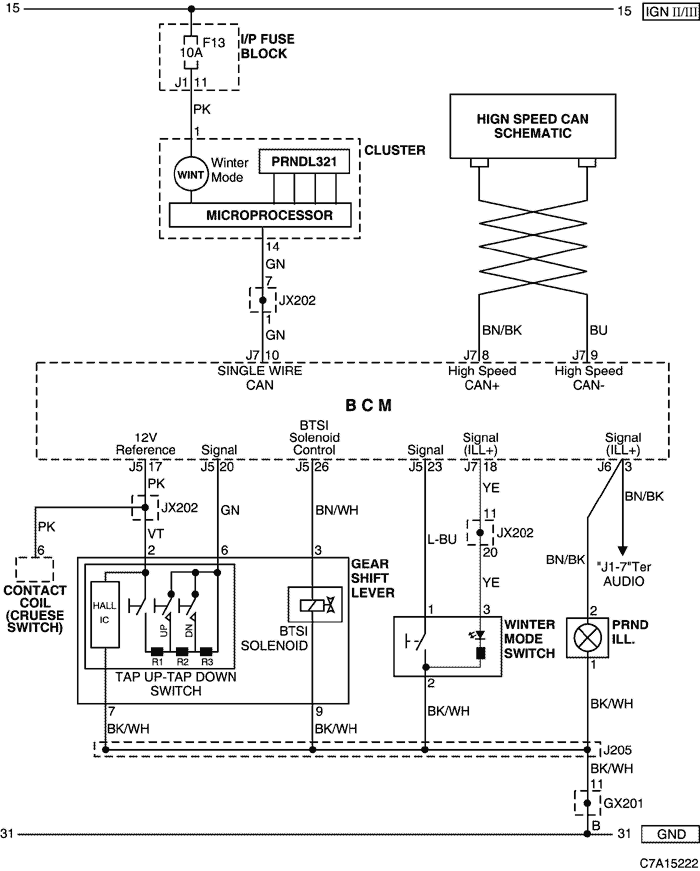
3) GEAR SHIFT LEVER, WINTER MODE SWITCH & CLUSTER CIRCUIT
a. CONNECTOR INFORMATION
CONNECTOR NO
(PIN NO, COLOR) | CONNECTING WIRING HARNESS | CONNECTOR POSITION |
| X204 (16 Pin, Black) | I.P - FATC | Behind the FATC |
| GX201 (Black/Gray) | I/P | Behind Steering Column - Lower |
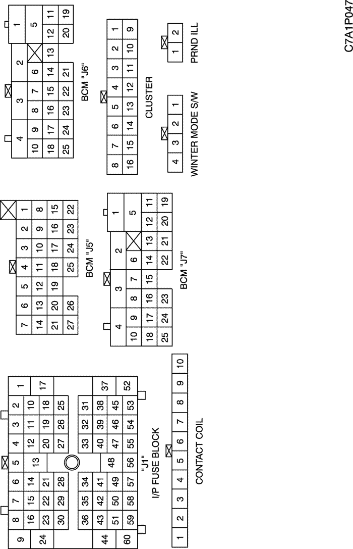
b. CONNECTOR IDENTIFICATION SYMBOL & PIN NUMBER POSITION
c. POSITION OF CONNECTORS AND GROUNDS
W/H INSTRUMENT PANEL
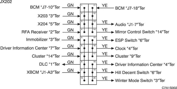
d. SPLICE PACK
JX202 (BLACK/PINK)
| © Copyright Chevrolet Europe. All rights reserved |