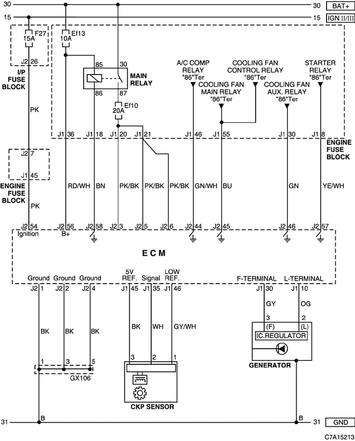
4. ECM (ENGINE CONTROL MODULE) : E77 (HFV6 3.2D)
1) BATTERY POWER SUPPLY, GROUND, GENERATOR & CKP SENSOR CIRCUIT
a. CONNECTOR INFORMATION
CONNECTOR NO
(PIN NO, COLOR) | CONNECTING WIRING HARNESS | CONNECTOR POSITION |
| Gx106 (Black/Gray) | Engine (DSL/HFV6) | Upper the Cylinder Head |
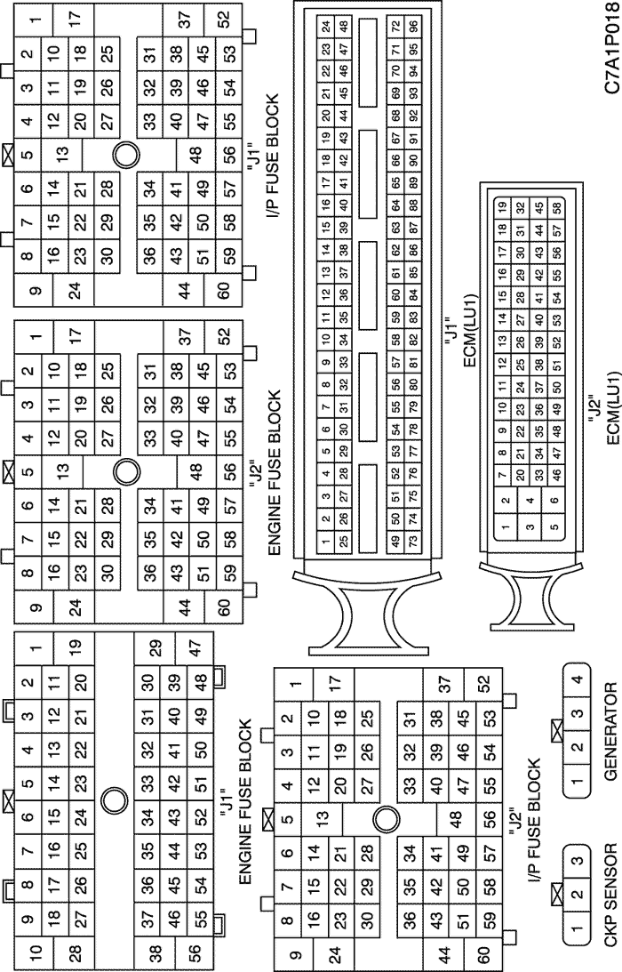
b. CONNECTOR IDENTIFICATION SYMBOL & PIN NUMBER POSITION
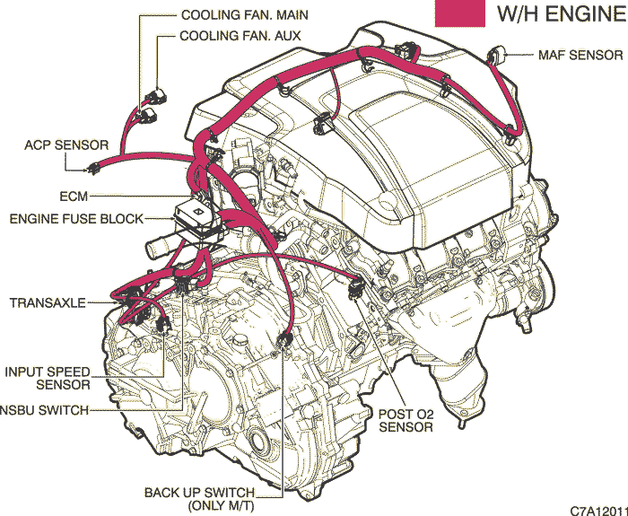
c. POSITION OF CONNECTORS AND GROUNDS
W/H ENGINE (LU1)
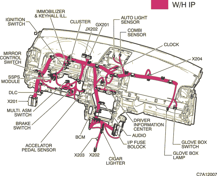
W/H INSTRUMENT PANNEL
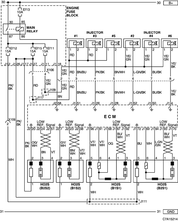
2) INJECTOR & HEATED O2 SENSOR CIRCUIT
a. CONNECTOR INFORMATION
CONNECTOR NO
(PIN NO, COLOR) | CONNECTING WIRING HARNESS | CONNECTOR POSITION |
| X106 (7 Pin, Black) | Engine - Fuel Injector (HVF6) | Upper the Cylinder Head |
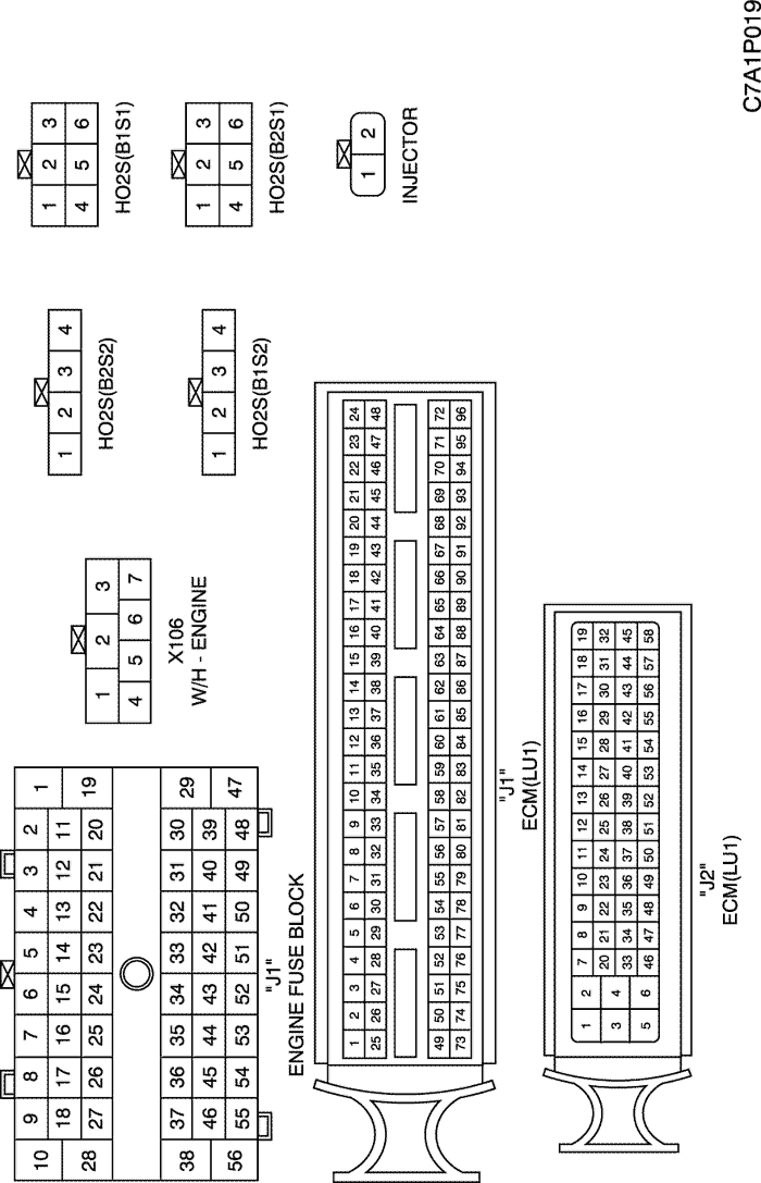
b. CONNECTOR IDENTIFICATION SYMBOL & PIN NUMBER POSITION
c. POSITION OF CONNECTORS AND GROUNDS
W/H ENGINE (LU1)
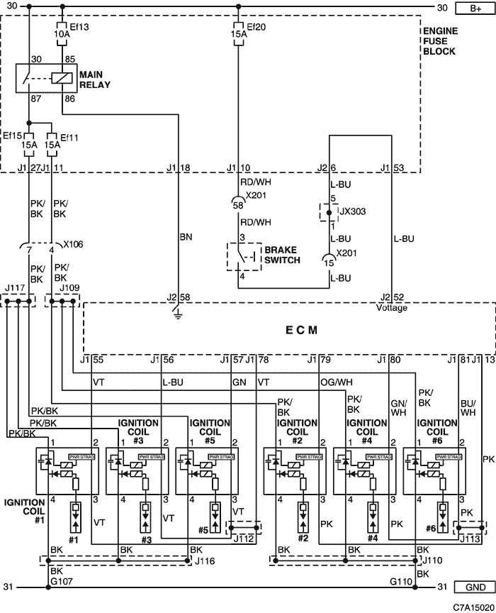
3) IGNITION COIL, BRAKE SWITCH CIRCUIT
a. CONNECTOR INFORMATION
CONNECTOR NO
(PIN NO, COLOR) | CONNECTING WIRING HARNESS | CONNECTOR POSITION |
| X106 (7 Pin, Black) | Engine - Fuel Injector (HVF6) | Upper the Cylinder Head |
| X201 (92 Pin, Black) | Body - I.P | Below to the "A" pillar |
| G107 | Fuel Injector (HFV6) | On the Cylinder Block |
| G110 | Fuel Injector (HFV6) | On the Cylinder Block |
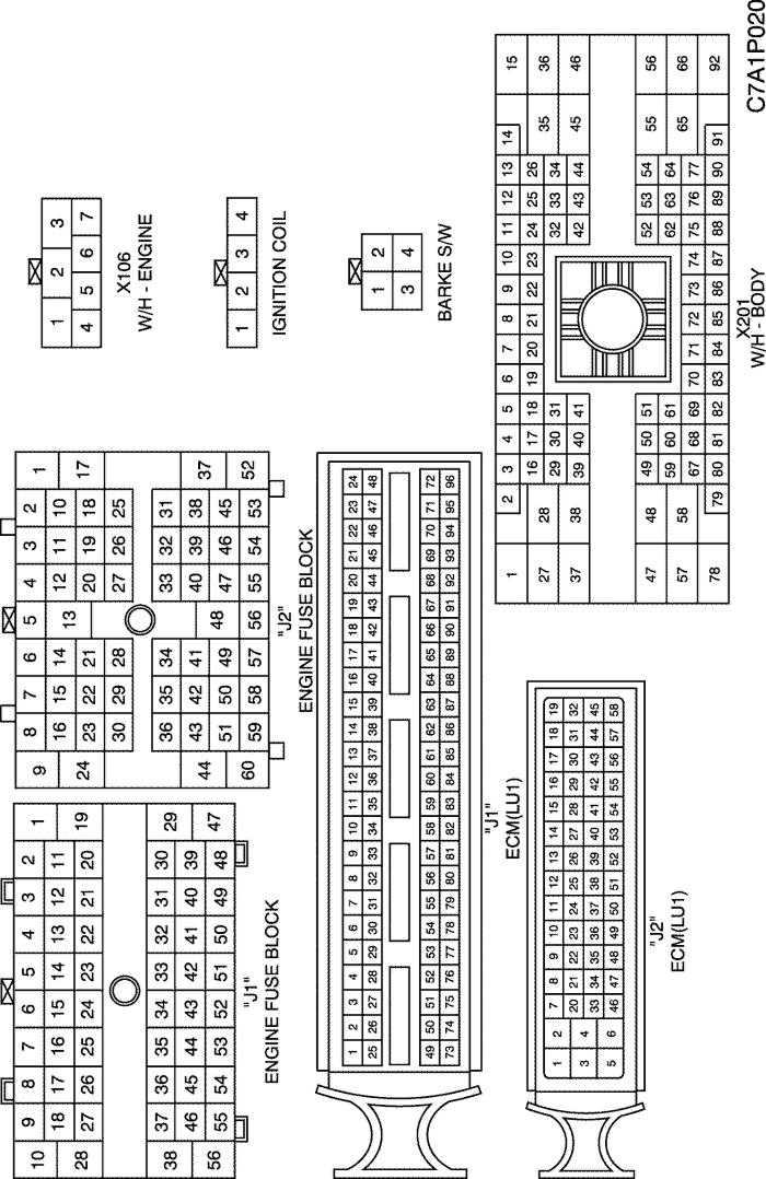
b. CONNECTOR IDENTIFICATION SYMBOL & PIN NUMBER POSITION
c. POSITION OF CONNECTORS AND GROUNDS
W/H ENGINE (LU1)
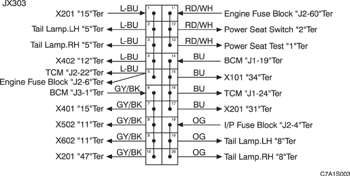
d. SPLICE PACK
JX303 (BLACK/BROWN)
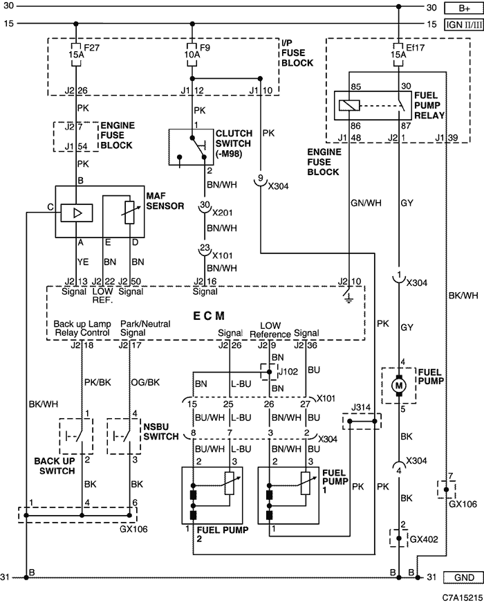
4) SENSOR (MAF, FUEL TANK LEVEL), FUEL PUMP & SWITCH (CLUTCH, BACK UP, NSBU) CIRCUIT
a. CONNECTOR INFORMATION
CONNECTOR NO
(PIN NO, COLOR) | CONNECTING WIRING HARNESS | CONNECTOR POSITION |
| X101 (36 Pin, Black) | Engine - Body | Behind the Engine Fuse Block |
| X201 (92 Pin, Black) | Body - I.P | Below to the "A" pillar |
| X304 (12 Pin, Black) | Fuel Sender - Body | Below the right "C" pillar |
| GX106 (Black/Gray) | Engine (DSL/HFV6) | Upper the Cylinder Head |
| GX402 (Black/Gray) | Body | Right the luggage compartment |
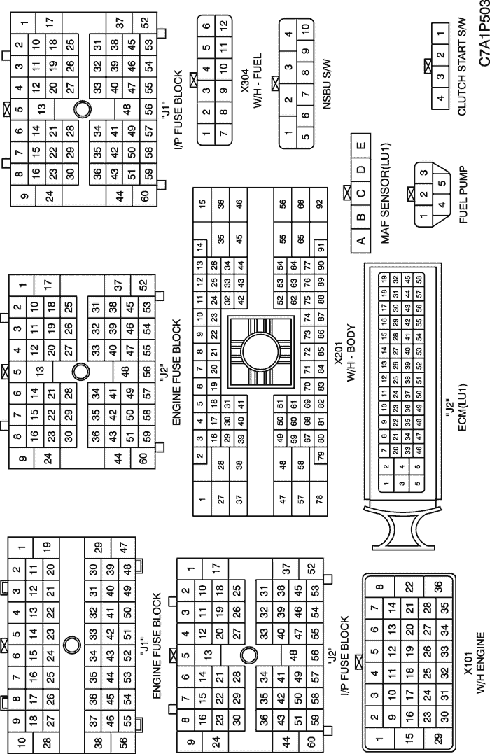
b. CONNECTOR IDENTIFICATION SYMBOL & PIN NUMBER POSITION
c. POSITION OF CONNECTORS AND GROUNDS
W/H ENGINE (LU1)
W/H INSTRUMENT PANNEL
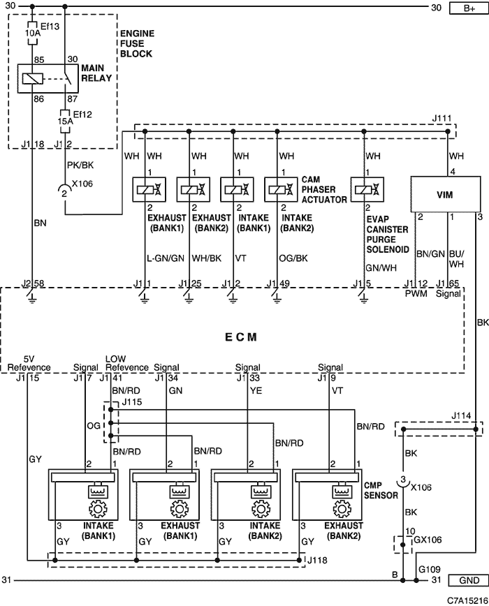
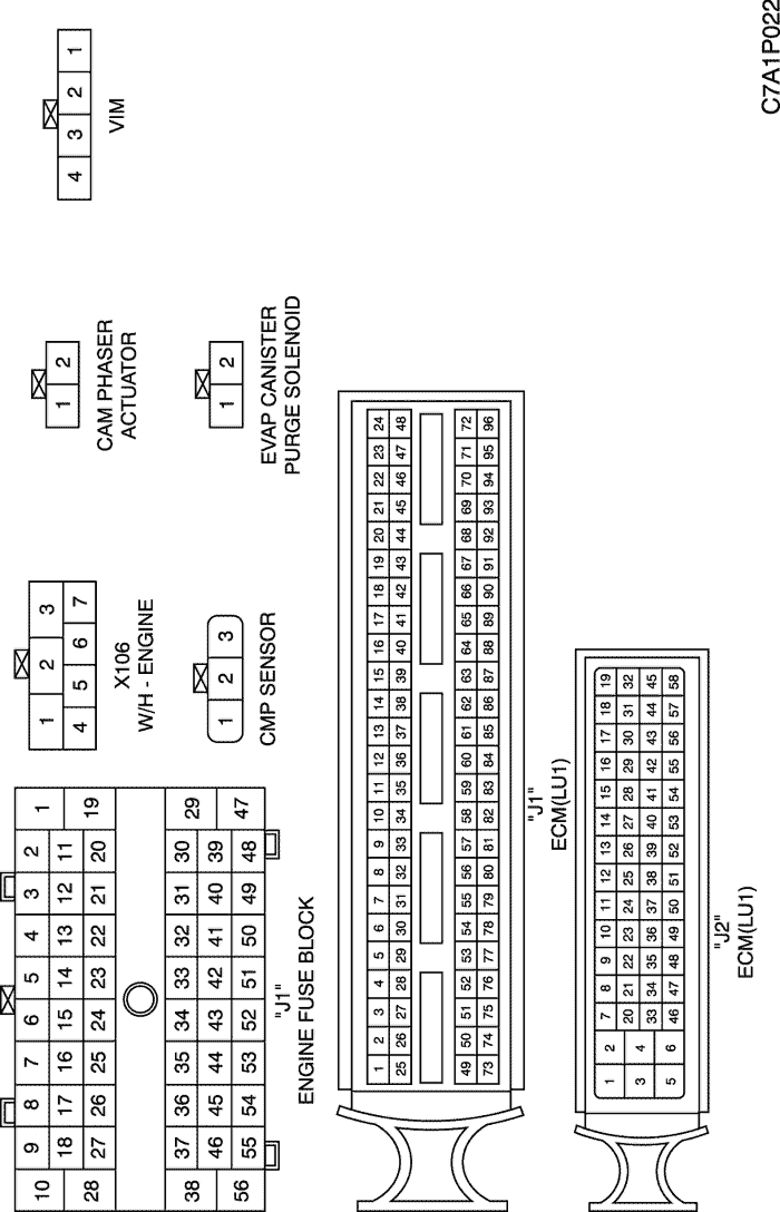
5) VIM, CAM PHASER ACTUATOR, EVAP CANISTER PURGE SOLENOID & CMP SENSOR CIRCUIT
a. CONNECTOR INFORMATION
CONNECTOR NO
(PIN NO, COLOR) | CONNECTING WIRING HARNESS | CONNECTOR POSITION |
| X106 (7 Pin, Black) | Engine - Fuel Injector (HVF6) | Upper the Cylinder Head |
| GX106 (Black/Gray) | Engine (DSL/HFV6) | Upper the Cylinder Head |
b. CONNECTOR IDENTIFICATION SYMBOL & PIN NUMBER POSITION
c. POSITION OF CONNECTORS AND GROUNDS
W/H ENGINE (LU1)
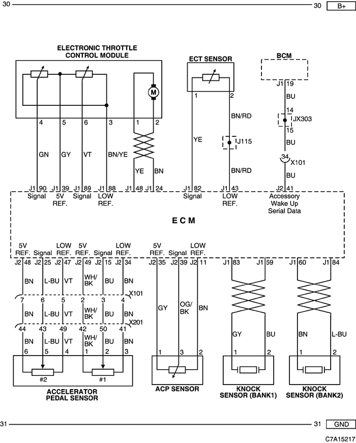
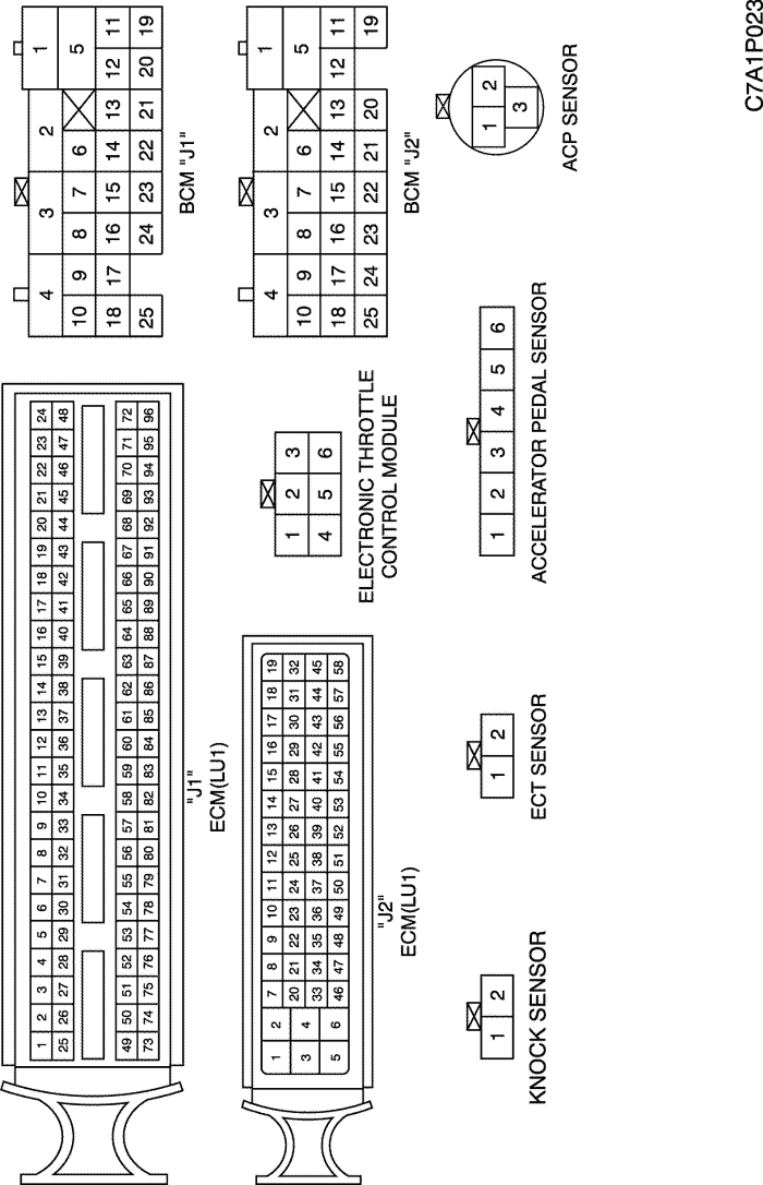
6) ETC MODULE, SENSOR (ECT, KNOCK, ACP & ACCELERATOR PEDAL) & BCM CIRCUIT
a. CONNECTOR INFORMATION
CONNECTOR NO
(PIN NO, COLOR) | CONNECTING WIRING HARNESS | CONNECTOR POSITION |
| X101 (36 Pin, Black) | Engine - Body | Behind the Engine Fuse Block |
| X201 (92 Pin, Black) | Body - I.P | Below to the "A" pillar |
b. CONNECTOR IDENTIFICATION SYMBOL & PIN NUMBER POSITION
c. POSITION OF CONNECTORS AND GROUNDS
W/H ENGINE (LU1)
W/H INSTRUMENT PANEL
d. SPLICE PACK
JX303 (BLACK/BROWN)
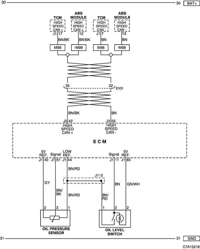
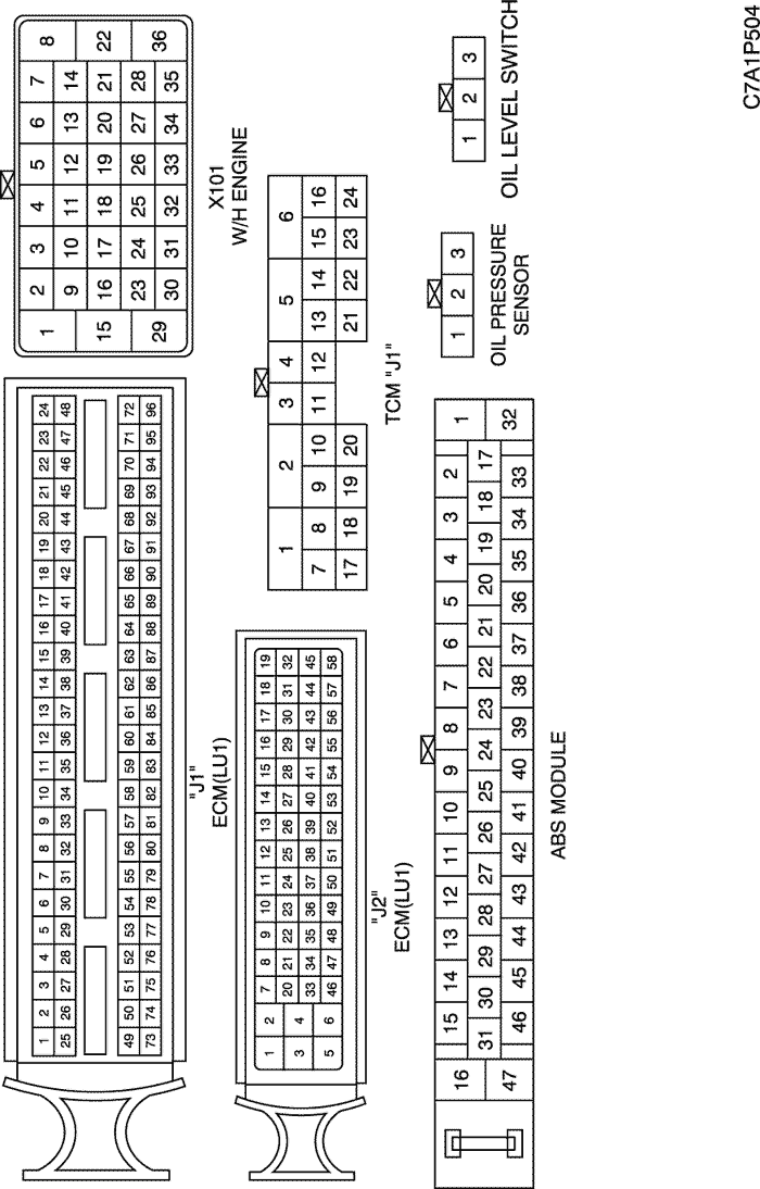
7) OIL PRESSURE SENSOR & OIL LEVEL SENSOR CIRCUIT
a. CONNECTOR INFORMATION
CONNECTOR NO
(PIN NO, COLOR) | CONNECTING WIRING HARNESS | CONNECTOR POSITION |
| X101 (36 Pin, Black) | Engine - Body | Behind the Engine Fuse Block |
b. CONNECTOR IDENTIFICATION SYMBOL & PIN NUMBER POSITION
c. POSITION OF CONNECTORS AND GROUNDS
W/H ENGINE (LU1)
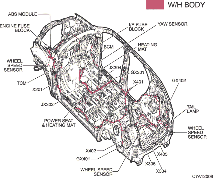
W/H BODY
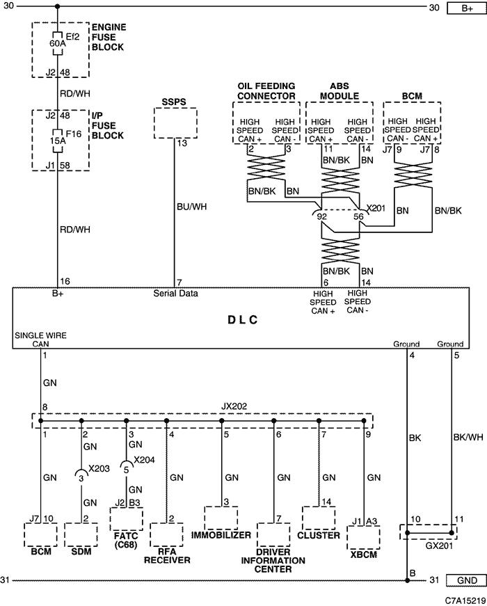
8) DLC CIRCUIT
a. CONNECTOR INFORMATION
CONNECTOR NO
(PIN NO, COLOR) | CONNECTING WIRING HARNESS | CONNECTOR POSITION |
| X201 (92 Pin, Black) | Body - I.P | Below to the "A" pillar |
| X203 (6 Pin, Colorless) | I.P - Air Bag | Below the floor console |
| X204 (16 Pin, Black) | I.P - FATC | Behind the FATC |
| GX201 (Black/Gray) | I/P | Behind Steering Column - Lower |
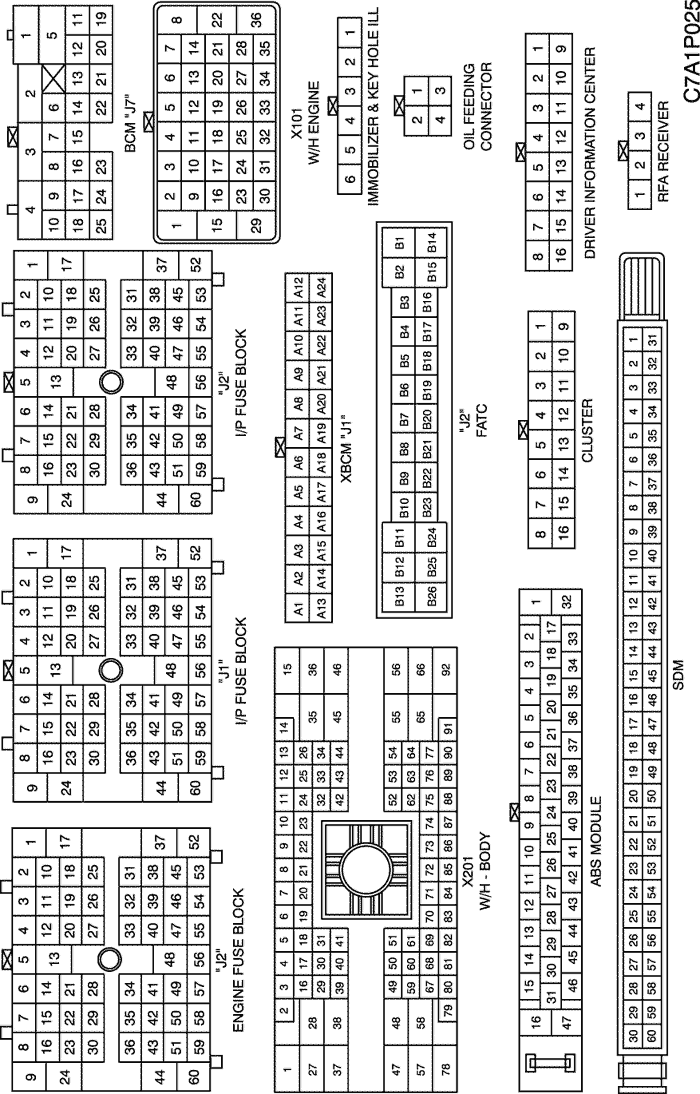
b. CONNECTOR IDENTIFICATION SYMBOL & PIN NUMBER POSITION
c. POSITION OF CONNECTORS AND GROUNDS
W/H INSTRUMENT PANEL
W/H BODY
d. SPLICE PACK
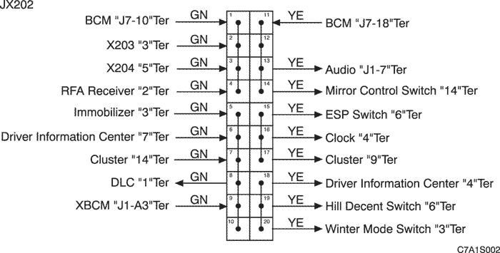
JX202 (BLACK/PINK)
| © Copyright Chevrolet Europe. All rights reserved |