SECTION
MAINTENANCE AND REPAIR
ON-VEHICLE SERVICE
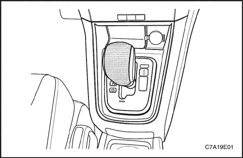


Cigar Jack
Removal Procedure
- Disconnect the negative battery cable.
- Remove the front console retainer. Refer to Section 9G, Interior Trim.
- Remove the front console cover trim panel.
- Disconnect the electrical connectors.
Installation Procedure
- Install the front console cover in the gear lever cover.
- Connect the electrical connector.
- Install the front console retainer. Refer to Section 9G, Interior Trim.
Tighten
Tighten the front console screws to 2 N•m (18 lb-in).
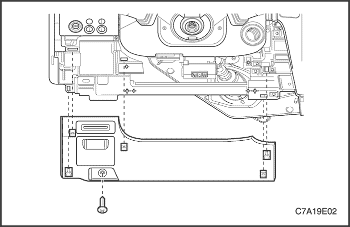
Instrument Panel Steering Colum Opening Pillar
Removal Procedure
- Remove the hood prime latch release handle. Refer to Section 9R, Body Front End.
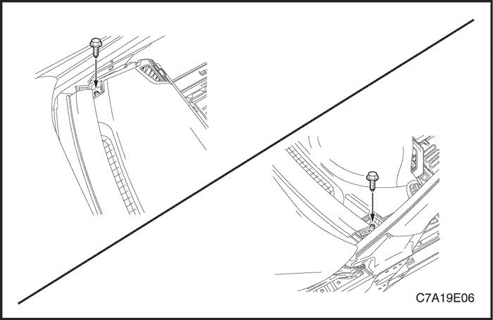
- Remove the screw and the instrument panel steering column opening pillar.
Installation Procedure
- Install the instrument panel steering column opening pillar.
Tighten
Tighten the instrument panel steering column opening pillar screw to 2 N•m (18 lb-in).
- Install the hood prime latch release handle. Refer to Section 9R, Body Front End.
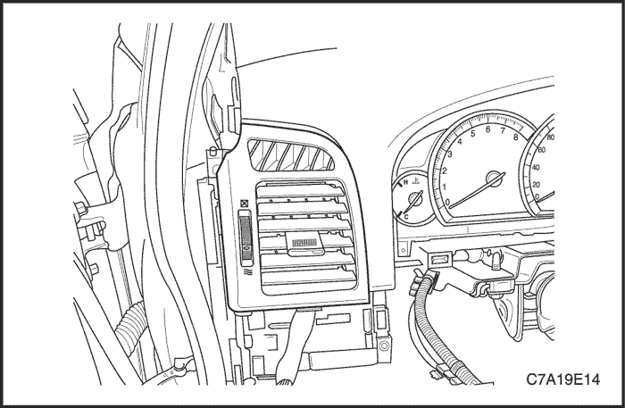
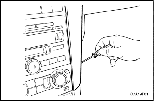
Instrument Panel Vents
Removal Procedure
- Remove the instrument cluster side cover.
- Pry off the vents by inserting a screwdriver.
Installation
- Press the vents onto the housing.
- Install the instrument cluster side cover.
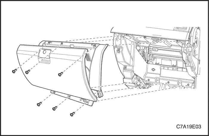
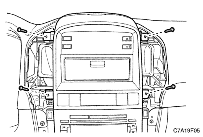
Instrument Comparment
Removal Procedure
- Disconnect the negative battery cable.
- Remove the screws at the base of the instrument compartment.
- Open and remove the screws.
- Disconnect the electrical connector.
- Remove the instrument compartment.
Installation Procedure
- Position the instrument compartment in the instrument panel.
- Connect the negative battery cable.
- Install the instrument compartment with the screws.
Tighten
Tighten the instrument compartment screws to 2 N•m (18 lb-in).
- Connect the negative battery cable.
Digital Clock
Removal Procedure
- Remove the I/P center trim panel.
- Remove the screws and I/P ACC bezel.
- Remove the screws and the digital clock.
Installation Procedure
- Install the digital clock with the screws.
Tighten
Tighten the digital clock screws to 2 N•m (18 lb-in).
- Install the I/P ACC bezel with the screws.
- Install the I/P center cluster trim panel.
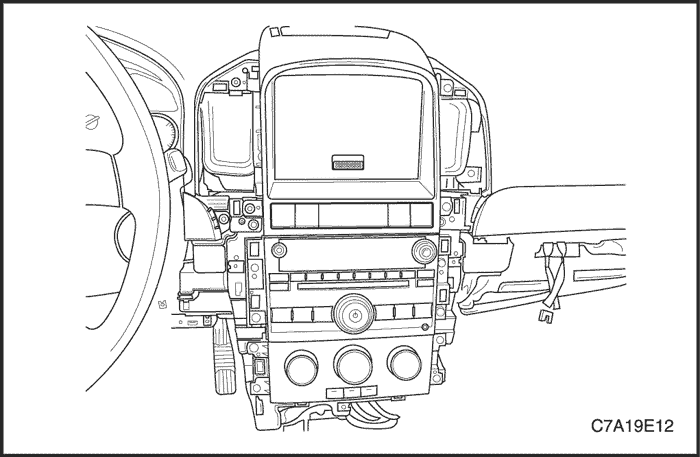
Instrument Cluster
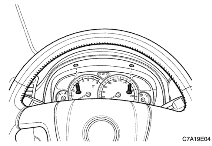
Removal Procedure
- Remove the instrument cluster trim panel.
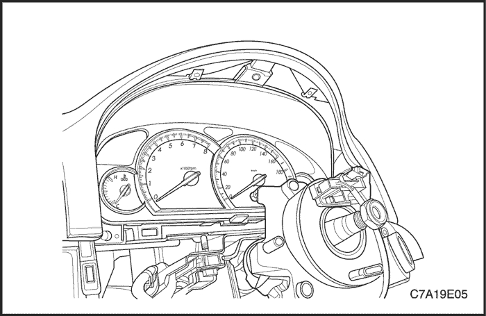
- Remove the screws and the instrument cluster.
Notice : Perform the SPO repregramming when instrument cluster replaced.
Installation Procedure
- Install the instrument cluster with the screws.
Tighten
Tighten the instrument cluster screws to 2 N•m (18 lb-in).
- Install the instrument cluster trim panel.
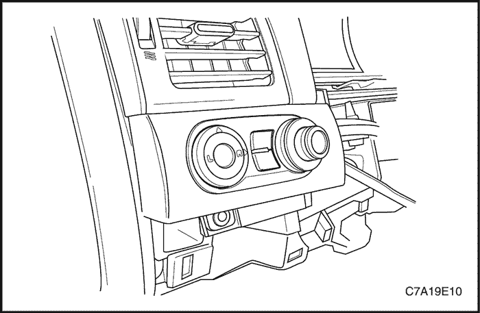
Instrument Cluster Dimmer/Headlamp Leveling/Mirror Control Switch
Removal Procedure
- Disconnect the negative battery cable.
- Remove the instrument cluster steering colum opening pillar.
- Remove the screw and the instrument cluster dimmer/headlamp leveling/mirror control switch.
- Disconnect the electrical connectors.
Installation Procedure
- Replace the appropriate switch.
- Connect the electrical connectors.
- Install the instrument cluster dimmer/headlamp leveling/mirror control switch with the screw.
Tighten
Tighten the instrument cluster dimmer/headlamp leveling/mirror control switch screws to 2 N•m (18 lb-in).
- Install the instrument cluster steering colum opening pillar.
- Connect the negative battery cable.
Driver Information Center
Removal Procedure
- Remove the instrument panel center trim panel.
- Remove the screws and the instrument panel accessory bezel.
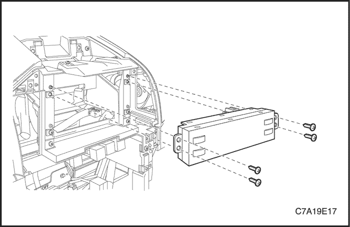
- Remove the screws and the driver information center.
Installation Procedure
Notice : Dissimilar metals in direct contact with each other may corrode rapidly. Make sure to use the correct fasteners to prevent premature corrosion.
- Install the driver information center with the screws.
Tighten
Tighten the driver information center with the screws to 2 N•m (18 lb-in).
- Install the instrument panel accessory bezel with the screws.
Tighten
Tighten the instrument panel accessory bezel with the screws to 2 N•m (18 lb-in).
- Install the instrument panel center trim panel.
Instrument Panel Lower Compartment
Removal Procedure
- Remove the instrument panel center trim panel.
- Remove the screws and the instrument panel accessory bezel.
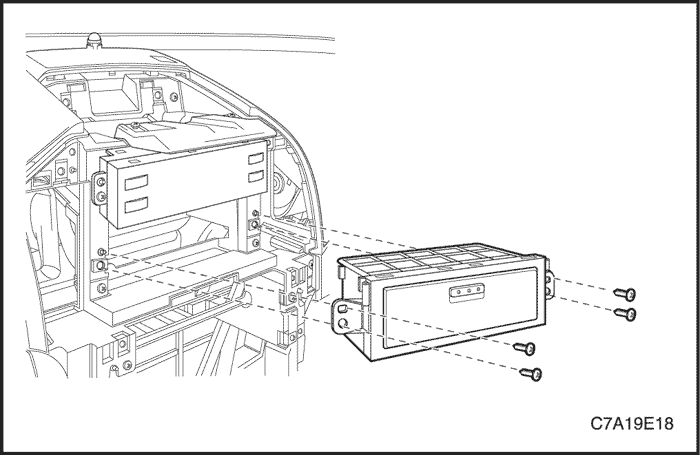
- Remove the screws and the instrument panel lower compartment.
Installation Procedure
Notice : Dissimilar metals in direct contact with each other may corrode rapidly. Make sure to use the correct fasteners to prevent premature corrosion.
- Install the instrument lower compartment with the screws.
Tighten
Tighten the instrument lower compartment with the screws to 2 N•m (18 lb-in).
- Install the instrument panel accessory bezel with the screws.
Tighten
Tighten the instrument panel accessory bezel with the screws to 2 N•m (18 lb-in).
- Install the instrument panel center trim panel.
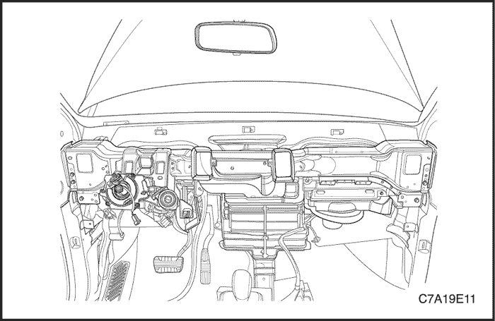
Instrument Panel
Removal Procedure
- Disconnect the negative battery cable.
- Remove the front, rear floor console. Refer to Section 9G, Interior Trim.
- Remove the audio system. Refer to Section 9F, AudioSystems.
- Remove the instrument cluster dimmer/headlamp leveling/mirror control switch assembly. Refer to " Instrument Cluster Dimmer/Headlamp Leveling Mirror Control Switch " in this section.
- Remove the instrument cluster trim panel.
- Remove the automatic temperature controls assembly. Refer to Section 7D, Automatic Temperature Control Heating, Ventilation, and Air Conditioning System.
- Remove the instrument cluster. Refer to " Instrument Cluster " in this section.
- Remove the kick panels.
- Remove the instrument compartment. Refer to " Instrument Compartment " in this section.
- Disconnect the instrument compartment electrical connectors.
- Remove the knee bolster.
- Remove the instrument panel side covers.
- Remove the instrument panel side covers.
- Remove the body control module. Refer to Section 9V, Body Control Module.
- Remove the nuts and the bolts securing the steering column.
- Remove the nuts and the bolts securing the steering column.
- Disconnect the steering column electrical connector.
- Disconnect the steering column electrical connector.
- Lower the steering column.
- Lower the steering column.
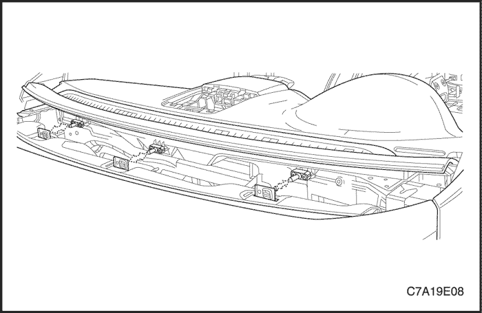
- Remove the instrument panel bolts below the windshield.
- Remove the instrument panel bolts below the windshield.
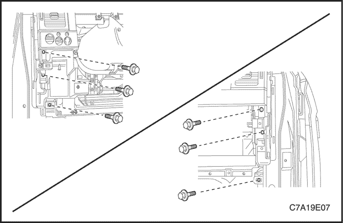
- Remove the fixing screws securing the instrument panel.
- Remove the fixing screws securing the instrument panel.
- Remove the bolts securing the sides of the instrument panel to the body.
- Remove the bolts securing the sides of the instrument panel to the body.
- Disconnect the instrument panel electrical connectors.
- Disconnect the instrument panel electrical connectors.
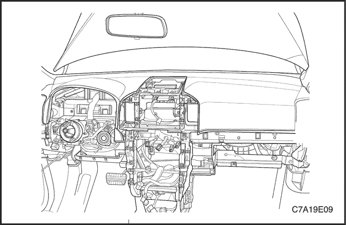
- Remove the instrument panel.
- Remove the instrument panel.
Installation Procedure
- Position the instrument panel in the vehicle.
- Connect the instrument panel electrical connectors.
Notice : Dissimilar metals in direct contact with each other may corrode rapidly. Make sure to use the correct fasteners to prevent premature corrosion.
- Install the bolts securing the sides of the instrument panel to the body.
- Install the bolts securing the sides of the instrument panel to the body.
Tighten
Tighten the instrument panel-to-body bolts to 23 N•m (17 lb-ft).
- Install the fixing screws securing the instrument panel.
- Install the fixing screws securing the instrument panel.
- Install the instrument panel bolts below the windshield.
- Install the instrument panel bolts below the windshield.
- Raise the steering column.
- Raise the steering column.
- Connect the steering column electrical connector.
- Connect the steering column electrical connector.
- Install the nuts and the bolts securing the steering column.
- Install the nuts and the bolts securing the steering column.
Tighten
Tighten the steering column nuts to 22 N•m (16 lb-ft).
Tighten the steering column bolts to 22 N•m (16 lb-ft).
- Install the body control module. Refer to Section 9V, Body Control Module.
- Install the body control module. Refer to Section 9V, Body Control Module.
- Install the knee bolsters.
- Connect the instrument compartment electrical connectors.
- Connect the instrument compartment electrical connectors.
- Install the instrument compartment. Refer to "Instrument Compartment"in this section.
- Install the kick panels.
- Install the instrument cluster. Refer to " Instrument Cluster "in this section.
- Install the automatic temperature controls assembly. Refer to Section 7D, Automatic Temperature Control Heating, Ventilation, and Air Conditioning System.
- Install the instrument cluster trim panel.
- Install the instrument cluster dimmer/headlamp leveling/mirror control switch assembly. Refer to "Instrument Cluster Dimmer Switch" in this section.
- Install the audio system. Refer to Section 9F, Audio systems.
- Install the sun sensor and the automatic temperature controls assembly. Refer to Section 7D, Automatic Temperature Control Heating, Ventilation, and Air Conditioning System.
- Install the floor console. Refer to Section 9G, Interior Trim.
- Connect the negative battery cable.
- Connect the negative battery cable.
GENERAL DESCRIPTIONAND SYSTEM OPERATION
Instrument Panel Vents
The center and the side vents in the instrument panel can be adjusted up and down and from side to side. The side vents can also be aimed toward the side windows to defog them.
Instrument Compartment
The instrument compartment can be opened by pulling up on the latch handle. The instrument compartment must be removed to gain access to the passenger side airbag module, (if equipped).
Digital Clock
The digital clock is located on the instrument panel above the radio. The clock is capable of an outside temperature display and a 12-hour or a 24-hour display.
Instrument Cluster
The instrument cluster is located above the steering column and in the instrument cluster trim panel. The instrument cluster contains the instruments that provide the driver with vehicle performance information. The instrument cluster contains a speedometer, a tachometer, an odometer, a trip odometer, a temperature gauge, a fuel gauge, and several indicator lamps.
Speedometer
The speedometer measures the speed of the vehicle in km/h or mph (with km/h). It consists of an instrument cluster gauge connected to the vehicle speed sensor on the transaxle output shaft.
Trip Odometer
The trip odometer measures the distance the vehicle has traveled since it was last reset. It consists of an instrument cluster gauge connected to the sending unit on the transaxle output shaft. The trip odometer can be reset to zero at any time so that the driver can record the distance traveled from any starting point.
Fuel Gauge
The fuel gauge consists of an instrument cluster gauge connected to a sending unit in the fuel tank.
The fuel gauge indicates the quantity of fuel in the tank only when the ignition is turned to ON or ACC. When the ignition is turned to LOCK or START, the pointer may come to rest at any position.
Temperature Gauge
The temperature gauge consists of an instrument cluster gauge connected to a temperature sensor that is in contact with the circulating engine coolant.
The temperature gauge indicates the temperature of the coolant. Prolonged driving or idling in very hot weather may cause the pointer to move beyond the center of the gauge. The engine is overheating if the pointer moves into the red zone at the upper limit of the gauge.
Tachometer
The tachometer measures the engine's speed in terms of thousands of revolutions per minute. It consists of an instrument cluster gauge connected to a sending unit in the engine control module.
Do not operate the engine in the red zone. Engine damage may occur.
Chime
The chime will sound to bring attention to one or more of the following conditions:
- The lights are on and the ignition is not in ACC, ON, or START.
- The ignition key is in the ignition switch when the driver's side door is open.
Voltage is supplied at all times through the fuse block to power the chime.
Driver Information Center
A Driver Informaion Center (DIC) is fitted to the instrument panel center. The DIC displays the functions of the heating and ventilation system and the trip computer. The DIC has no serviceable items. If any component fails to function, the module must be replaced.


