Engine Cranks But Does Not Run
Circuit Description
The Engine Cranks but Does Not Run diagnostic table is an organized approach to identifying a condition that causes an engine not to start. The Engine Cranks but Does Not Run diagnostic table directs the service technician to the appropriate system diagnosis.
The Engine Cranks But Does Not Run diagnostic table assumes the following:
- The batteries are completely charged.
- The cranking speed is within specifications.
- There is adequate fuel in the fuel tanks.
Diagnostic Aids
If the cause of an engine cranks but will not run condition has not been found, inspect for the following conditions:
- Hard starting only in cold ambient temperatures. These may cause an intermittent condition that may not occur in the service bay:
- Fuel heater inoperative.
- Ice blockage at the fuel pickup in the fuel tank--This will be a high vacuum in the supply lines while cranking, and the problem will disappear after the vehicle is brought in the service bay. It may also exhibit a start and stall condition or a starting condition with no acceleration.
- Water or foreign material in fuel system
- A basic engine problem
Test Description
The numbers below refer to the step numbers on the diagnostic table.
- This step tests for an ignition 1 voltage supply to the engine control module (ECM).
- In some cases, no compression, possibly with excessive fuel, in a single cylinder can cause a no start.
Engine Cranks but Does Not Run
| Step | Action | Value(s) | Yes | No |
| 1 | Did you perform the Diagnostic System Check? | - | Go to Step 2 | |
| 2 | - Turn ON the ignition, with the engine OFF.
- Observe the DTC Information with a scan tool.
Does the scan tool display DTCs related to the fuel pressure regulator, fuel rail pressure (FRP) sensor, CKP sensor, CMP sensor, ECM internal error, 5V reference circuits, glow plug control module, or immobilizer fuel enable signal? | - | Go to applicable DTC table | Go to Step 3 |
| 3 | Is the customer's concern with a fuel smell or fuel leak? | - | | Go to Step 4 |
| 4 | Observe the Actual Fuel Rail Pressure parameter with a scan tool. Is the parameter at the specified value? | 0.5V | Go to Step 5 | Go to Step 10 |
| 5 | Observe the Ignition 1 signal parameter with a scan tool. Is the Ignition 1 signal parameter at the specified value? | 0.5V | Go to Step 6 | Go to Step 13 |
| 6 | Inspect for the following conditions: - Excessive fuel in the engine oil.
Did you find and correct the condition? | - | Go to Step 19 | Go to Step 7 |
| 7 | Perform the Engine Compression Test. Did you find and correct the condition? | - | Go to Step 20 | Go to Step 8 |
| 8 | Important : Important: If there is high resistance in the signal or low reference circuits of the crankshaft position (CKP) sensor, the Engine Speed parameter of the scan tool will display a value more than 0. It will not be an accurate measure of engine speed, and can cause an Engine Cranks but does Not Run condition. Test the CKP sensor signal and low reference circuits for high resistance. Did you find and correct the condition? | - | Go to Step 19 | Go to Step 9 |
| 9 | Inspect for the following conditions: - A plugged air filter
- A collapsed air intake duct
- The fuel heater is inoperative. If the customer concern is that the engine will not start when ambient temperatures are less than 2-4°C (35-40°F), refer to Fuel Heater Inoperative.
- A restricted exhaust system
Did you find and correct the condition? | - | Go to Step 19 | Go to Diagnostic Aids |
| 10 | - Disconnect the fuel rail pressure sensor.
- Observe the Actual Fuel Rail Pressure parameter on the scan tool.
Does the Actual Fuel Rail Pressure parameter measure less than the specified value? | - | Go to Step 11 | Go to Step 12 |
| 11 | Test the fuel rail pressure sensor signal circuit for a short to ground. Did you find and correct the condition? | - | Go to Step 19 | Go to Step 16 |
| 12 | Test the fuel rail pressure sensor circuits for high resistance. Did you find and correct the condition? | - | Go to Step 19 | Go to Step 14 |
| 13 | - Test the ignition 1 voltage circuit of the engine control module (ECM) for a short to ground, a high resistance or an open.
- Replace the fuse, if necessary.
Did you find and correct the condition? | - | Go to Step 19 | Go to Step 15 |
| 14 | Test for an intermittent or for a poor connection at the fuel rail pressure sensor. Did you find and correct the condition? | - | Go to Step 19 | Go to Step 17 |
| 15 | - Clean and tighten the ECM shared ground.
- Attempt to start the engine.
Does the engine start? | - | Go to Step 19 | Go to Step 16 |
| 16 | Test for an intermittent and for a poor connection at the ECM. Did you find and correct the condition? | - | Go to Step 19 | Go to Step 18 |
| 17 | Replace the fuel rail pressure sensor. Did you complete the replacement? | - | Go to Step 19 | - |
| 18 | Replace the ECM. Did you complete the replacement? | - | Go to Step 19 | - |
| 19 | - Clear any DTCs with a scan tool.
- Attempt to start the engine.
Does the engine start and continue to run? | - | Go to Step 20 | Go to Step 2 |
| 20 | - Allow the engine to idle until normal operating temperature is reached.
- Observe the DTC Information with a scan tool.
Are any DTCs displayed? | - | Go to applicable DTC table | System OK |
Fuel Rail Pressure Regulator Diagnosis
The Fuel Rail Pressure Regulator graphing procedure offers valuable information on regulator performance by comparing desired and actual fuel rail pressure. An almost perfect comparison between actual rail pressure and desired rail pressure is found on a fairly new, low mileage engine. A minor ripple is acceptable behavior for the fuel rail pressure regulator and is seen on high mileage engines. A "shark tooth" fluctuation in actual fuel rail pressure indicates a sticking pressure regulator.
- Start and idle the engine.
- Observe the scan tool live plot for sharp changes or "shark tooth" pattern in the Actual Fuel Rail Pressure while performing the following actions:
- Idling the engine
- Shifting the transmission from Park to Drive and back to Park
- Turning the steering from left stop position to right stop position
- Turning the air conditioning ON and OFF
- If there is a violent fluctuation in the Actual Fuel Rail Pressure , as seen in the surging graph below, replace the fuel pressure regulator.
Good Fuel Pressure Regulator Graph, New/Low Mileage
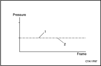


- Actual Fuel Rail Pressure
- Desired Fuel Rail Pressure
Good Fuel Pressure Regulator Graph, High Mileage
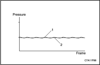
- Actual Fuel Rail Pressure
- Desired Fuel Rail Pressure
Sticking Fuel Pressure Regulator Graph
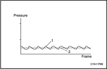
- Actual Fuel Rail Pressure
- Desired Fuel Rail Pressure
Fuel Pump Electrical Circuit Diagnosis
Circuit/System Description
An electric fuel pump is used to prime the fuel system after changing the fuel filter or servicing the fuel system. The fuel pump is powered by the fuel pump relay. The fuel pump relay is controlled by the engine control module (ECM). The ECM enables the fuel pump when the ignition is turned ON, and will continue to run for a while, or until the engine starts. If the ignition is left in the ON position, the pump will run for about four seconds. The ECM will also turn OFF the fuel pump if incorrect voltage is detected on the control circuit. The ECM will need to be powered down with a key cycle during diagnosis or after repairs, before it will command the fuel pump ON again.
Diagnostic Aids
The following conditions may cause the fuel pump fuse to open:
- A faulty fuse
- An intermittent short to ground in the supply voltage circuit of the fuel pump
- The fuel pump has an intermittent internal condition
Circuit/System Testing
- Inspect the fuel pump fuse.
- Inspect the fuel pump fuse.
- If the fuel pump fuse is open, test the battery positive voltage circuit and the fuel pump supply voltage circuit for a short to ground or a faulty fuel pump.
- Turn ON the ignition, with the engine OFF.
- Command the fuel pump ON and OFF with a scan tool. The fuel pump relay should click and turn ON and OFF with each command.
- If the fuel pump operates continuously, test for a faulty relay or a short to voltage in the fuel pump supply voltage circuit.
- If the fuel pump does not turn ON and OFF, replace the fuel pump relay.
- Probe the battery positive voltage circuit of the fuel pump relay with a test lamp that is connected to a good ground.
- If the test lamp does not illuminate, repair the open in the battery positive voltage circuit.
- Connect a fused jumper wire between the battery positive voltage circuit and the supply voltage circuit of the fuel pump relay.
- If the fuel pump operates, test for an intermittent and for a poor connection at the fuel pump relay, or a faulty fuel pump relay.
- If the fuel pump does not operate, test for an open or high resistance in the supply voltage circuit, or ground circuit of the fuel pump.
- If all circuits test normal and the fuel pump relay operates properly, replace the fuel pump.
Fuel System Diagnosis
Fuel System Description
Fuel is drawn by the supply pump through a pre-filter screen in the tank and to the engine through the fuel supply lines. The fuel passes through the fuel filter/heater element housing, which combines a water separator, fuel heater element and a filter element. The fuel is then delivered to the high-pressure fuel injection pump. Scan tool output control function or repetition of ignition key ON/OFF is used to prime the fuel system after changing the fuel filter or servicing the fuel system by activating the fuel pump without engine running. If the fuel system is not supplying enough fuel, a driveability concern may occur. If air is being drawn into the fuel injection system, a Cranks But Will Not Run or Hart Start symptom could exist.
High Pressure System
The fuel injection pump is engine-driven by the timing belt. From the high-pressure fuel injection pump, the pressurized fuel flows to the common rail. Common rail supplies pressurized fuel to the fuel injectors. The fuel rail pressure (FRP) sensor is mounted on the common rail.
Return System
The fuel return system routes fuel from the fuel injectors, fuel rail, and the fuel injection pump. The fuel pressure regulator is located in the common rail. The return fuel travels to the fuel tank. If the high side fuel pressure becomes excessive, the fuel pressure regulator releases the fuel into the fuel return system.
Diagnostic Aids
The following conditions may cause an air leak into the fuel supply system:
- Deformed or cut O-rings at the fuel supply line connections
- Improperly seated fuel supply line fittings
- Porous or weathered rubber fuel supply lines
Circuit/System Testing
- Disconnect the fuel supply line to the fuel injection pump.
- Install a fuel pressure gage between fuel injection pump inlet port and fuel supply line.
- Prime the fuel system.
- Command the fuel pump ON with a scan tool and observe the fuel pressure gage to ensure that fuel pressure is present. Visually inspect the engine and chassis for leaks or damage to the fuel hoses, fuel lines, and fuel system components.
- Repair any leaks or replace any components found to be damaged or leaking.
- If the fuel pump did not run and fuel pressure was not observed, refer to Fuel Pump Electrical Circuit Diagnosis.
- If the fuel pump did run and fuel pressure was not observed, inspect the fuel feed line for a vacuum leak.
- If leaks or damage were not found on the fuel system, turn OFF the fuel pump and remove the fuel pressure gage.
- Install a transparent hose between the fuel injection pump inlet port and fuel supply line. Create a vertical loop in the hose to observe the incoming fuel for air bubbles.
- Command the Fuel Pump ON with a scan tool and prime the fuel system until all air has been purged. Start and run the engine for at least 10 minutes to allow the fuel system to stabilize.
- If air bubbles were observed entering the transparent hose, test the fuel sender for leaks.
- If air bubbles are still present after replacing the fuel sender, refer to Diagnostic Aids.
- If no air bubbles are present after replacing the fuel sender, remove the transparent hose and run the engine to ensure no fuel leaks exist.
Fuel Return System Diagnosis
Fuel System Description
Fuel is drawn by the supply pump through a pre-filter screen in the tank and to the engine through the fuel supply lines. The fuel passes through the fuel filter/heater element housing, which combines a water separator, fuel heater element and a filter element. The fuel is then delivered to the high-pressure fuel injection pump. Scan tool output control function or repetition of ignition key ON/OFF is used to prime the fuel system after changing the fuel filter or servicing the fuel system by activating the fuel pump without engine running. If the fuel system is not supplying enough fuel, a driveability concern may occur. If air is being drawn into the fuel injection system, a Cranks But Will Not Run or Hart Start symptom could exist.
High Pressure System
The fuel injection pump is engine-driven by the timing belt. From the high-pressure fuel injection pump, the pressurized fuel flows to the common rail. Common rail supplies pressurized fuel to the fuel injectors. The fuel rail pressure (FRP) sensor is mounted on the common rail.
Return System
The fuel return system routes fuel from the fuel injectors, fuel rail, and the fuel injection pump. The fuel pressure regulator is located in the common rail. The return fuel travels to the fuel tank. If the high side fuel pressure becomes excessive, the fuel pressure regulator releases the fuel into the fuel return system.
Diagnostic Aids
Bent or pinched fuel return lines on the engine can cause a restricted fuel return flow.
Fuel Return System Diagnosis
| Step | Action | Value(s) | Yes | No |
| 1 | Important : Do not apply more than the specified air pressure to the return line. - Disconnect the return line at the engine.
- Remove the fuel filler cap.
- Apply 1 psi air at the fuel return line that leads back to the tank.
- Listen at the filler tube for air flowing from the tank.
Did air flow from the filler tube? | - | Go to Step 6 | Go to Step 2 |
| 2 | - Disconnect the return line at the fuel sender assembly.
- Retest using 1 psi at the fuel return line back to the tank.
Did air flow from the return line? | - | Go to Step 3 | Go to Step 4 |
| 3 | Replace the fuel sender assembly. Did you complete the replacement? | - | Go to Step 6 | - |
| 4 | - Lift the vehicle.
- Inspect the return line for restrictions between the fuel tank and engine.
Did you find and correct the condition? | - | Go to Step 6 | Go to Step 5 |
| 5 | Replace the fuel return line between the engine and the fuel tank. Did you complete the replacement? | - | Go to Step 6 | - |
| 6 | - Install and connect all components or fuel lines that were previously removed or disconnected.
- Operate the vehicle in order to verify the repairs.
Did you correct the condition? | - | System OK | Go to applicable DTC table |
Fuel Leaks
- Remove the air cleaner assembly.
- Clean all of the fuel lines between the fuel injection pump and the fuel injectors using brake cleaning solvent, and let dry.
- Add 250ml of oil dye to the fuel tank.
- Start and idle the engine for 3-5 minutes.
- Inspect for fuel leaks around the fuel injection pump, fuel rails, and fuel injector supply lines. Tighten or replace any leaking lines or components.
- A fuel leak may be caused by restricted return fuel lines.
Fuel Injector Balance Test With Scan Tool (Cylinder Compression Test)
Circuit Description
When conditions arise in cylinder balancing, a scan tool output control test function is provided to help in locating the cause. A compression test can be used to decide whether the cause should be attributed to the engine or the injection system. Once the problem has been limited to the injectors, further tests can determine which injector is responsible for the condition in cylinder balancing.
The test consists of 3 modes (A, B, C), which are conducted in different test conditions.
Circuit/System Testing
Using a scan tool, perform the compression tests following the instructions displayed on the screen.
Mode A: Output of rotational speeds of selected cylinders during a compression test
All injections are inhibited in order to allow a compression test by actuating the starter without starting the engine. The rotational engine speed at each top dead center (TDC) is provided. A lower cylinder selective engine speed in compression to the others shows a higher compression of this cylinder. A higher cylinder selective engine speed a lower compression. The fuel balancing control (FBC) correction values in this test are zero. Note that the purpose of the test is to see the relative performance of each cylinder. The higher or the lower compression mentioned here does not necessarily mean that the actual engine cylinder compression performance as a gauge pressure is showing a same property.
Mode B: Quantity correction output by selected cylinder
In this test mode, the engine is running with the fuel balancing control (FBC) correction values enabled. The correction quantity shows an offset, which is added to the injected quantity to establish a vibration-free running of the engine. The cylinder selective engine speed is also provided. A higher cylinder balancing quantity correction shows an injector, which needs more time to inject an amount of fuel to produce the requested torque.
Mode C: Output of rotational speeds of selected cylinders for shut off cylinder balancing quantities
In this test mode, the engine is running with the fuel balancing control (FBC) correction values disabled. The cylinder selective engine speed is provided and the engine running behavior without FBC values can be monitored..
Contaminants-In-Fuel Diagnosis
Fungi and other microorganisms can survive and multiply in diesel fuel if water is present. The fungi can be present in any part of the fuel handling system. These fungi grow into long strings and will form into large globules. The growths appear slimy and are usually black, green, or brown. The fungi may grow anywhere in the fuel but are most plentiful where diesel fuel and water meet. As the fuel is agitated, when service station tanks are being filled, fungi are distributed throughout the tank and may be pumped into a vehicle.Fungi use the fuel as their main energy supply and need only trace amounts of water and minerals. As they grow and multiply, they change fuel into water, sludge, acids, and products of metabolism. The most common symptom is fuel filter plugging, however various metal fuel system components including fuel sender assembly, pipes, fuel injectors, and fuel injection pump can corrode.
Caution: Avoid physical contact with the biocides in order to avoid personal injury.
If fungi have caused fuel system contamination, use a diesel fuel biocide to sterilize the fuel system. Do not exceed the dosage recommended on the label. Discontinue the use of a biocide when towing a trailer. It is permissible to have biocide in the fuel when starting to tow, but do not add any biocide while towing.
Steam cleaning may be necessary if most of the fungus growth cannot be removed with biocides.
The presence of water or gasoline in diesel fuel may also cause injection pump and fuel injector damage.
This procedure checks for the presence of water and gasoline in diesel fuel that may cause fuel injection pump and fuel injector damage.
Remove and inspect the fuel filter.
- If water, gasoline or fungi/bacteria are not present, end the inspection.
- If water or fungi/bacteria are present, go to Cleaning Water from the Fuel System.
- If gasoline is present, go to Cleaning Gasoline from the Fuel System.
Cleaning Water from the Fuel System
- Disconnect the negative battery.
- Remove the sending unit.
- Inspect the fuel tank and the fuel sender for rust, fungi or bacteria. If there is rust, replace the rusted components.
- Clean the inside of the fuel tank and the fuel sender with hot water.
- Use compressed air in order to dry the fuel tank and the fuel sender.
- Disconnect the ends of the following lines:
- The fuel filter inlet line (both ends)
- The fuel filter outlet line (both ends)
- The fuel return line (both ends)
- Inspect each of the pipes and lines.
- Replace any rusted pipes.
- Clean the inside of the fuel filter housing.
- Dry the fuel filter housing with compressed air.
- Dry the inside of each line with low pressure air.
- Remove the ignition1 relay.
- Install a new fuel filter.
- Install the sending unit.
- Add clean diesel fuel to the primary tank until the tank is ¼ full.
- Reconnect the following lines:
- The fuel filter inlet line
- The fuel filter outlet line
- The fuel return line (tank end)
- Connect the batteries.
- Prime the fuel system.
- Install a hose on the fuel return line at the engine, and insert other end into a 7.6 liters (2 gallon) metal container.
- Crank the engine for 30 second time intervals, with 1 minute cool-down periods. Continue until 3.8 liters (1 gallon) of fuel has passed into the container.
- Connect the fuel return line.
- Install the ignition1 relay.
- Start and run the engine.
- Stop the engine.
- Clean any fuel spillage from the engine.
- Fill the fuel tank and add a biocide, if needed.
Cleaning Gasoline from the Fuel System
- Drain the fuel tank.
- Fill the fuel tank to ¼ full.
- Remove the ignition1 relay.
- Loosen the fuel filter drain and connect a hose to the filter that flows into a metal container.
- Operate the fuel pump with a scan tool until clean fuel flows from the fuel filter drain into the metal container.
- Close the fuel filter drain and disconnect the hose.
- Install a hose on the fuel return line at the engine, and insert the other end into a 7.6 liters (2 gallon) metal container.
- Crank the engine for 30 second time intervals, with 1 minute cool-down periods. Continue until 3.8 liters (1 gallon) of fuel has passed into the container.
- Reconnect the fuel return line.
- Install the ignition1 relay.
- Attempt to start and run the engine for 15 minutes. If the engine does not start, prime the fuel system.
- Stop the engine.
- Clean any fuel spillage from the engine.
- Clear the engine of any diagnostic trouble codes (DTCs).
Fuel Heater Inoperative
Circuit Description
The fuel manager/filter assembly consists of the fuel heater, the water-in-fuel sensor, and a filter. The filter contains the coalescer, the device that combines small droplets of water into larger ones, and the filter/separator.
As the fuel enters the filter, the fuel passes through the fuel heater. The heater contains a thermostatic switch that opens or closes to turn the heater OFF or ON, depending on the temperature of the fuel.
The fuel then passes through the filter and the water coalescer, where the droplets of water in the fuel combine into larger drops that fall into the water reservoir in the filter. When fuel flows from the fuel manager/filter assembly to the high pressure pump, the fuel is clean and free of water.
The fuel heater is operated by the ECM. The fuel temperature sensor is a negative temperature coefficient (NTC) thermistor and sends the fuel temperature information to the ECM.
| Step | Action | Value(s) | Yes | No |
| 1 | Did you perform the Diagnostic System Check? | - | Go to Step 2 | |
| 2 | - Disconnect the fuel heater harness connector.
- Turn ON the ignition with the engine OFF.
- Probe the fuel heater ignition 1 voltage circuit with a test lamp connected to a good ground.
- Command the fuel heater ON using a scan tool.
Does the test lamp illuminate? | - | Go to Step 3 | Go to Step 5 |
| 3 | Probe the fuel heater ground circuit with a test lamp connected to B+. Does the test lamp illuminate? | - | Go to Step 4 | Go to Step 7 |
| 4 | - Remove the fuel filter/heater element housing from the vehicle.
- Command the fuel heater ON using a scan tool.
- Observe the heating element.
Does the temperature of the fuel heater increase? | - | Go to Step 9 | Go to Step 8 |
| 5 | Repair the open in the ignition 1 voltage circuit between the fuel heater harness connector and the fuse. Did you complete the repair? | - | Go to Step 9 | - |
| 6 | Repair the short to ground on the ignition 1 voltage circuit. Did you complete the repair? | - | Go to Step 9 | - |
| 7 | Repair the open in the ground circuit between the fuel heater harness connector and the chassis ground. Did you complete the repair? | - | Go to Step 9 | - |
| 8 | Replace the fuel heater. Did you complete the replacement? | - | Go to Step 9 | - |
| 9 | Operate the vehicle under which the problem was noted. Does the system operate properly? | - | System OK | Go to Step 2 |
Data Link References
This table identifies which serial data link that a particular module uses for in-vehicle data transmission. Some modules may use more than one data link to communicate. Some modules may have multiple communication circuits passing through them without actively communicating on that data link. This table is used to assist in correcting a communication malfunction.
Control Module | Data Link Type | Diagnostic Procedure Reference |
Body Control Module (BCM) | High Speed GMLAN / Low Speed GMLAN | Scan Tool Does Not Communicate with High Speed GMLAN Device |
Electronic Brake Control Module (EBCM) | High Speed GMLAN | Scan Tool Does Not Communicate with High Speed GMLAN Device |
Electronic Climate Control (ECC) | Low Speed GMLAN | Scan Tool Does Not Communicate with Low Speed GMLAN Device |
Engine Control Module (ECM) | High Speed GMLAN | Scan Tool Does Not Communicate with High Speed GMLAN Device |
Export Body Control Module (XBCM) | Low Speed GMLAN | Scan Tool Does Not Communicate with Low Speed GMLAN Device |
Instrument Panel Cluster (IPC) | Low Speed GMLAN | Scan Tool Does Not Communicate with Low Speed GMLAN Device |
Remote Function Actuation (RFA) | Low Speed GMLAN | Scan Tool Does Not Communicate with Low Speed GMLAN Device |
Sensing and Diagnostic Module (SDM) | Low Speed GMLAN | Scan Tool Does Not Communicate with Low Speed GMLAN Device |
Transaxle Control Module (TCM) | High Speed GMLAN | Scan Tool Does Not Communicate with High Speed GMLAN Device |
Transfer Case Control Module (TCCM) | High Speed GMLAN | Scan Tool Does Not Communicate with High Speed GMLAN Device |
Vehicle Theft Deterrent (VTD) Module | Low Speed GMLAN | Scan Tool Does Not Communicate with Low Speed GMLAN Device |
Scan Tool Does Not Power Up
Circuit Description
The data link connector (DLC) is a standardized 16 cavity connector. Connector design and location is dictated by an industry wide standard, and is required to provide the following:
- Scan tool power battery positive voltage at terminal 16
- Scan tool power ground at terminal 4
- Common signal ground at terminal 5
The scan tool will power up with the ignition OFF. Some modules however, will not communicate unless the ignition is ON and the power mode master (PMM) module sends the appropriate power mode message.
Test Description
The number below refers to the step number on the diagnostic table.
| Step | Action | Value(s) | Yes | No |
| 1 | Test the battery positive voltage circuit of the data link connector (DLC) for an open or a short to ground. Did you find and correct the condition? | - | | Go to Step 2 |
| 2 | Test the ground circuits of the DLC for an open or high resistance. Did you find and correct the condition? | - | | Go to Step 3 |
| 3 | Inspect for poor connections and terminal tension at the DLC. Did you find and correct the condition? | - | | Go to Step 4 |
| 4 | The scan tool may be malfunctioning. Refer to the scan tool user guide. Did you obtain a properly operating scan tool? | - | | - |
Scan Tool Does Not Communicate with High Speed GMLAN Device
Circuit Description
The GMLAN serial data circuits are controller area network (CAN) high speed serial data buses used to communicate information between the control modules. Typical data transmission speeds must be high enough to ensure that a required real-time response is maintained. On this vehicle there are 2 utterly different types of GMLAN serial data circuits, the High speed 2-wire circuit and Low speed single wire circuit. The GMLAN serial data circuits also communicate directly to the data link connector (DLC). Messages are interpreted by the externally connected CANdi module which acts as a transceiver for the scan tool.
Modules connected to the high speed GMLAN serial data circuits monitor for serial data communications during normal vehicle operation. Operating information and commands are exchanged among the modules when the ignition switch is in any position other than OFF. The high speed GMLAN serial data circuits must be operational for the vehicle to start due to body control module (BCM) and engine control module (ECM) communications. The vehicle theft deterrent (VTD) module and ECM exchange information using the BCM as the gateway module allowing communication between the high and low speed serial data busses. The low speed GMLAN serial data circuit must also be operational for vehicle starting. The high speed GMLAN serial data buss uses two 120 ohm terminating resistors that are in parallel with the high speed GMLAN (+) and (-) circuits.
Diagnostic Aids
- Use the “Data Link References” to identify the high speed GMLAN serial data modules.
- When testing for a short between the high speed GMLAN (+) and (-) circuits (ECM disconnected), a resistance reading of 120 ohms is normal. To test for shorts to voltage or ground in the high speed GMLAN (+) and (-) circuits ensure that all modules, resistors and the scan tool are disconnected from the buss. A normal resistance reading across the high speed GMLAN buss with the resistors, all modules and scan tool disconnected is infinite ohms.
- This test is used for a total high speed GMLAN communication failure. If only 1 module is not communicating and sets no DTC, ensure that the vehicle is equipped with the module, then use DTC U0100-U0299 for diagnostics.
- Use the DMM MIN/MAX function to capture/locate intermittent conditions.
- The engine will not start when there is a total malfunction of the high speed GMLAN serial data bus. The following conditions may cause a total loss of high speed GMLAN data communication:
- A short between high speed GMLAN (+) and high speed GMLAN (-) circuits
- Any of the high speed GMLAN serial data circuits shorted to ground or voltage
- A module internal malfunction that causes a short to voltage or ground on the high speed GMLAN circuits
- An inoperative BCM
Circuit/System Testing
- With a scan tool verify that communication is not available for all high speed serial data modules.
- If any high speed module communicates and any DTC beginning with a U exists, refer to applicable DTC table for diagnostics
- If any high speed module communicates and no DTC beginning with a U exists, Refer to DTC U0100-U0299 for diagnostics
- Test for less than 1 ohm of resistance between the DLC ground circuit terminal 5 and ground.
- If greater than 1 ohm, test the ground circuit for an open/high resistance
- Ignition OFF, disconnect the harness connector of the BCM.
- Ignition ON, test for battery voltage between each voltage input circuit of the BCM and ground.
- If less than battery voltage, test each voltage output circuit of the BCM for a short to ground, and each voltage input circuit of the BCM for a short to ground or and open/high resistance.
- Test for less than 1 ohm of resistance between each ground circuit of the BCM and ground.
- If greater than 1 ohm, repair the ground circuit for an open/high resistance.
- Ignition OFF. Reconnect the harness connector of the BCM. Disconnect the transfer case control module (TCCM) connector if equipped with all wheel drive (AWD), or terminator resistor connector if equipped with front wheel drive (FWD).
- Attempt to communicate with the BCM. Communication should not be available.
- If communication is established, replace the TCCM or the terminator resistor.
- Test the serial data circuits for a short together, a short to ground, or a short to voltage between the BCM and the TCCM or the terminator resistor.
- Ignition OFF, disconnect the harness connector of the ECM.
- Attempt to communicate with the BCM. Communication should not be available.
- If communication is established, replace the ECM.
- Ignition OFF, disconnect the harness connector of the TCM.
- Attempt to communicate with the BCM. Communication should not be available.
- If communication is established, test the serial data circuits for a short together, a short to ground, or a short to voltage between the ECM and the TCM. If the circuits test normal, replace the TCM.
- Ignition OFF, disconnect the harness connector of the electronic brake control module (EBCM).
- Attempt to communicate with the BCM. Communication should not be available.
- If communication is established, test the serial data circuits for a short together, a short to ground, or a short to voltage between the TCM and the EBCM. If the circuits test normal, replace the EBCM.
- Ignition OFF, disconnect the harness connector of the BCM.
- Test for less than 1.0 volt between the high speed GMLAN serial data circuits of the DLC and ground.
- If greater than 1.0 volt, repair the serial data circuit for a short to voltage.
- Test for infinite resistance between the high speed GMLAN serial data circuit of the DLC and ground.
- If less than infinite resistance, repair the serial data circuit for a short to ground.
- Test for infinite resistance between the high speed GMLAN serial data (+) and (-) circuits of the DLC.
- If less than infinite resistance, repair the serial data circuits for a short between them.
- If the circuits test normal, replace the BCM.
Scan Tool Does Not Communicate with Low Speed GMLAN Device
Circuit Description
The GMLAN serial data circuits are controller area network (CAN) high speed serial data buses used to communicate information between the control modules. Typical data transmission speeds must be high enough to ensure that a required real-time response is maintained. On this vehicle there are 2 utterly different types of GMLAN serial data circuits, the High speed 2-wire circuit and Low speed single wire circuit. The GMLAN serial data circuits also communicate directly to the data link connector (DLC). Messages are interpreted by the externally connected CANdi module which acts as a transceiver for the scan tool.
Modules connected to the low speed GMLAN serial data circuit monitor for serial data communications during normal vehicle operation. Operating information and commands are exchanged among the modules when the ignition switch is in any position other than OFF. The low speed GMLAN serial data circuit must be operational for the vehicle to start so the vehicle theft deterrent (VTD) module and body control module (BCM) can communicate.
Diagnostic Aids
- Use the “Data Link References” to identify the low speed GMLAN serial data modules.
- This test is used for a total low speed GMLAN communication failure. If only 1 module is not communicating and sets no DTC, ensure that the vehicle is equipped with the module, then use DTC U0100-U0299 for diagnostics.
- An open in the low speed GMLAN serial data circuit between the splice pack and a module(s) will only affect the specific module(s). This type of failure will set a loss of communication DTC for each module effected, and the other modules will still communicate. Depending on which module is affected, the vehicle may not start.
- An open between the data link connector (DLC) and the splice pack will only effect the communication with the scan tool. The vehicle modules will still communicate, and the vehicle will start.
- Use the DMM MIN/MAX function to capture/locate intermittent conditions.
- The engine will not start when there is a total malfunction of the low speed GMLAN serial data circuit. The following conditions may cause a total loss of low speed GMLAN data communication:
- The low speed GMLAN serial data circuit shorted to ground or voltage.
- A module internal malfunction that causes a short to voltage or ground on the low speed GMLAN circuit.
Circuit/System Testing
- Test for less than 1.0 ohm of resistance between the DLC ground circuit terminal 5 and ground.
- If greater than 1.0 ohm, repair the ground circuit for an open/high resistance.
- Ignition OFF, disconnect the harness connector at the low speed splice pack.
- Ignition ON, test for less than 1.0 volt between the low speed GMLAN serial data circuit of the DLC and ground.
- If greater than 1.0 volt, repair the serial data circuit for a short to voltage.
- Test for infinite resistance between the serial data circuit of the DLC and ground.
- If less than infinite resistance, repair the serial data circuit for a short to ground.
- Test for less than 1.0 ohm of resistance in the serial data circuit between the DLC and the splice pack.
- If greater than 1.0 ohm, repair the serial data circuit for an open/high resistance.
- Install a 3-amp fused jumper wire between terminal 1 and terminal 8 of the splice pack. Install another 3-amp fused jumper wire to terminal 1.
- Using the open end of the extra jumper wire from the terminal 1, connect to the other terminals on the splice pack one at a time and attempt to establish communications with each module connected to the extra jumper wire. At least one module should be able to communicate.
- If communications can't be established with any module, test the serial data circuit of the BCM for a short to voltage, short to ground or open/high resistance. If the circuit tests normal, replace the BCM.
- If communications can’t be established with a specific module, test the serial data circuit of the module that caused loss of communication for a short to voltage, short to ground or open/high resistance. If the circuit tests normal, replace the module.
- If all circuits test normal, test or replace the splice pack.
Engine Control Module Programming And Setup (Z20S Diesel Engine)
ECM Replacement
- The following procedures are required to be performed when replacing an ECM:
- ECM programming (SPS Programming)
- Theft deterrent programming (Immobilizer)
- The following items are required to be performed after programming a new ECM:
- Tire size setup (Tire Circumference Coding)
- Injector flow rate setup (Programming Injector Quantity Adjustment (IQA)) or IMA coding - Using a scan tool, note the stored injector flow rate before changing an ECM and restore the value after programming a new ECM.
- Remaining engine oil life setup – Using a scan tool, note the stored engine oil life data before changing an ECM and restore the value after programming a new ECM.
- Vehicle Configuration programming
- Zero Fuel Correction (ZFC) EEPROM values reset and ZFC quick learn activation.
- DPF EEPROM values reset
ECM Reprogramming
The following items are required to be input when re-programming an ECM (ECM is not replaced):
- No special action is needed after reprogramming an ECM.
Setup for Component Replacement
The replacement of some components will require a setup procedure for complete repair.
The following setup procedures are required to be performed when replacing components:
- ECM programming (SPS Programming)
- Whenever the ECM is replaced
- Remaining engine oil life setup
- Whenever the engine oil is replaced.
- Whenever the ECM is replaced.
- Tire size setup (Tire Circumference Coding)
- Whenever the different from previous size tires are installed.
- Zero Fuel Correction (ZFC) EEPROM values reset
- Whenever the injectors are replaced.
- Whenever the fuel rail pressure (FRP) sensor or the entire fuel rail is replaced. In this case ZFC quick learn must be activated as well.
- Whenever the ECM is replaced.
- DPF EEPROM values reset
- Whenever the Diesel Particulate Filter (DPF) is replaced.
- Whenever the DPF pressure difference sensor is replaced.
- Whenever the injectors are replaced.
- Whenever the ECM is replaced.
- DPF service regeneration
- Whenever the soot loading level has increased past maximum threshold (48g) and triggered power-reduction. As a result, normal regeneration is inhibited and DTC P2463 is stored.
- Whenever the soot loading level has reached between 24g and 48g while the following DTCs are stored in the ECM. In these cases, service regeneration should be performed after appropriate repair or replacement has been made on each DTCs;
Sensor reference voltageP060B, P0651 Exhaust gas temperature deviation from setpointP1446, P1447, P244C, P244D Intake air temperature (IAT1) sensorP0110 Engine oil dilutedP253F InjectorP0201, P0202, P0203, P0204, P062B, P1224, P1227, P122A, P1233, P2146, P2149, Fuel systemP0087, P0088, P0089, P0090, P0190, P0191, P2293, P2294 DPFP2031, P2080, P2084, P20E2, P2458, P2463- Injector flow rate setup (Programming Injector Quantity Adjustment (IQA)) or IMA coding
- Whenever the injectors are replaced.
- Whenever the position of the injectors are changed.
- Whenever the ECM is replaced.
Diesel Particulate Filter (Dpf) Service Regeneration
If a vehicle is returned to service with either an active or inactive DPF related DTC, a function is available in the software that allows a scan tool to initiate a controlled regeneration to help pinpoint the components requiring repair. In addition, if the soot loading level has increased past maximum threshold and triggered power-reduction and regeneration inhibition, the service mode is the only way to regenerate the DPF and remove the power-reduction (service mode ignores many of the abort conditions required for normal driving regeneration). The service mode is also useful to validate that any repairs to the DPF system have been successful.DPF diagnostics are active during service regeneration, so checking for DPF DTCs during the service regeneration will help determine if any issues are present. If any DTCs occur, repair the issue and rerun the service mode.
Caution :
- During service regeneration, tailpipe outlet temperature will be over 550°C (1022°F). Make sure any person to be away from the tail pipe.
- Ensure that the vehicle is positioned in the open and over a heat-resistant surface.
- Engine and exhaust system damage can occur due to improper usage of the service regeneration.
- Do not initiate the service regeneration if non-DPF faults are present on the vehicle. Engine or exhaust system damage could occur if the service regeneration is initiated with malfunctioning engine components.
- Make sure the soot does not leak from the end of the DPF before performing the service regeneration. Check for sign of soot at the tail pipe first. If soot present, inspect the DPF outlet pipe. A presence of soot in the rear-end cross-section of the DPF means that the DPF filtering performance has severely decreased. If the soot leaks from the end of the DPF, replace the DPF.
Important :
- Check coolant level before and after the procedure.
- Oil changes may be necessary after running the service mode. Every time the service regeneration is run, the oil viscosity will be reduced. As a rule of thumb, it is recommended to change the engine oil after service regeneration if the engine is past 80% of the oil change interval. In addition, if more than 3 service regenerations are run back-to-back, change the engine oil regardless of the oil life remaining.
- Allow the vehicle to cool down after the service regeneration. Good practice is to run the engine at 1500 RPM in order to let the exhaust cool more uniformly, preventing excessive heat build up.
DPF Regeneration Procedure
- Install a scan tool.
- Check the coolant for proper level.
- Select the DPF service regeneration in the scan tool output control menu.
- Follow the corresponding instructions displayed on the screen of the scan tool.
Note : The procedure can be interrupted at any time in an emergency by switching off the ignition. Depressing the brake returns the engine to idling speed. If the scan tool is used to interrupt the procedure, the engine slowly returns to idling speed.
- After finishing the DPF service regeneration, switch off the engine and allow the vehicle to cool down. Good practice is to run the engine at 1500 RPM in order to let the exhaust cool more uniformly, preventing excessive heat build up.
- Check the coolant for proper level.
| © Copyright Chevrolet Europe. All rights reserved |


