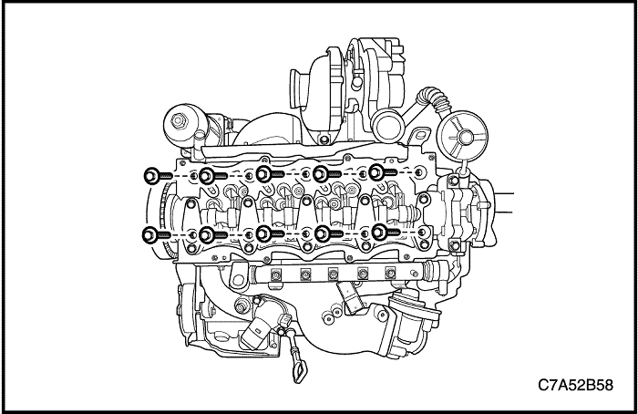
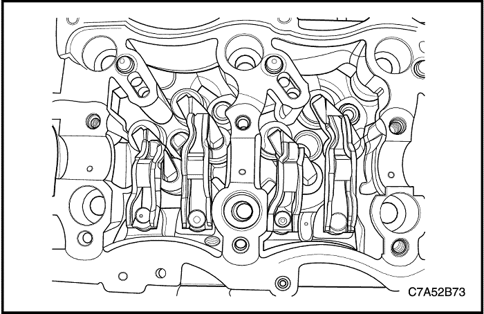
Remove the intake/exhaust roller finger-followers.
Remove the intake/exhaust valve bridge.
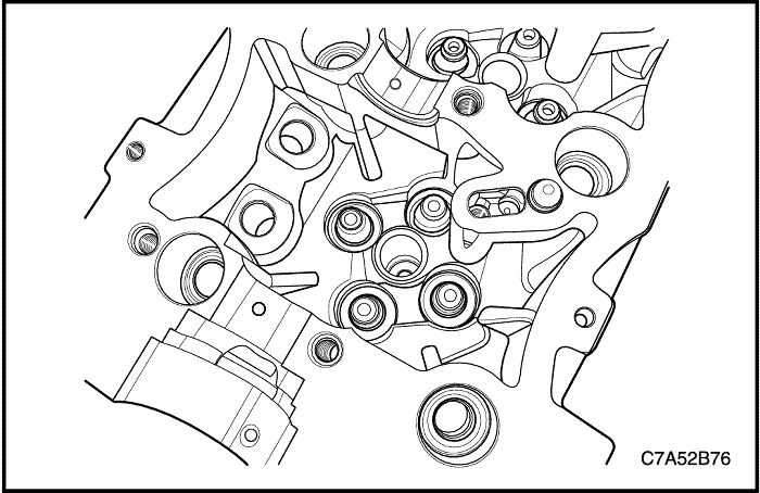
Remove the intake/exhaust valve lash adjuster.
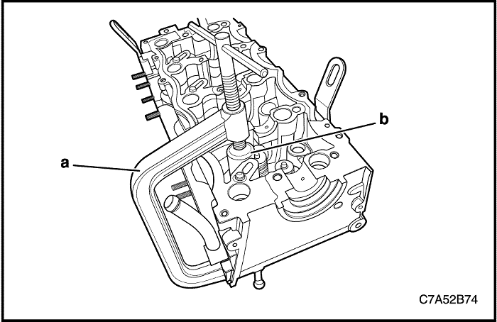
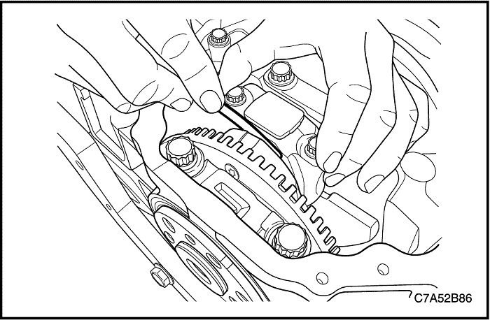
Install the valve spring compressor 09916-14510(a) with the valve spring compression adapter EN-48247(b) to the cylinder head.
Turn the handle of the valve spring compressor 09916-14510 for compressing the valve spring.
Remove the valve key.
Remove the valve spring retainer.
Remove the valve spring.
Remove the valves.
Remove the valve stem oil seal.
Cylinder Head Inspection
Clean the sealing surfaces.
Inspect the cylinder head for the following.
Cracks, damage or pitting in the combustion chambers.
Debris in the oil galleries. Continue to clean the galleries until all debris is removed.
Coolant leaks or damage to the deck face sealing surface.
Damage to any gasket surfaces.
Damage to any threaded bolt holes.
Burnt or eroded areas in the combustion chamber.
Cracks in the exhaust ports and combustion chambers.
External cracks in the water passages.
Restrictions in the intake or exhaust passages.
Restrictions in the cooling system passages.
Rusted, damaged or leaking core plugs.
If the cylinder head is cracked or damaged, it must be replaced. No welding or patching of the cylinder head is recommended.
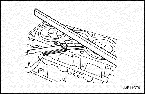
Measure the clearance between the straight–edge and the cylinder head deck face using a feeler gauge at four points along the straight–edge.
Check the sealing surfaces for deformation and warpage. The cylinder head sealing surfaces must be flat within 0.05 mm (0.002 in.) maximum.
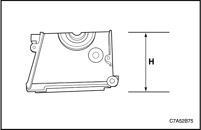
Measure the height of the cylinder head from sealing surface to sealing surface. The cylinder head height should be 129.9 to 130.1 mm (5.1142 to 5.1220 in.). If the cylinder head height is out of specifications, replace the cylinder head.
Valve Inspection
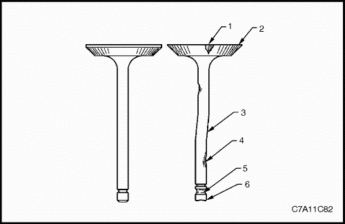
Inspect the valve for damage from the head to tip for the following conditions.
pitting in the valve seat area (1)
lack of valve margin (2)
bending in the valve stem (3)
pitting or excessive wear in the stem (4)
worn valve key grooves (5)
worn valve tip (6)
Replace the valve if any of these conditions exist.
Inspect the valve springs. If the valve spring ends are not parallel, replace the valve spring.
Inspect the valve spring seating surface of the valve rotators for wear or gouges. Replace as required.
Cleaning Procedure
Clean the cylinder head.
Clean the valve guides.
Clean all of the threaded holes.
Clean the valves of carbon, oil, and varnish.
Assembly Procedure
Lubricate the valve stems with engine oil.
Carefully install the valves in their original positions.
Install the valve stem oil seal.
Install the valve spring.
Install the valve spring seat.
Install the valve.
Install the valve spring retainer.
Compress the valve springs with the valve spring compressor 09916-14510(a) and the valve spring compression adapter EN-48247(b).
Install the valve key.
Remove the valve spring compressor 09916-14510(a) and the valve spring compression adapter EN-48247(b).
Install the valve lash adjusters.
Install the valve bridges.
Install the valve roller finger-followers.
Coat the sealant(LOCTITE 573) on the camshaft front/rear cap sealing surface.
Install the camshaft.
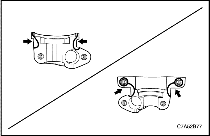
Install the camshaft cap.
Tighten
Tighten the camshaft cap bolts to 28 N•m (20.7 lb-ft).
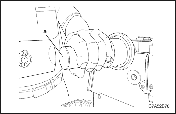
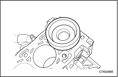
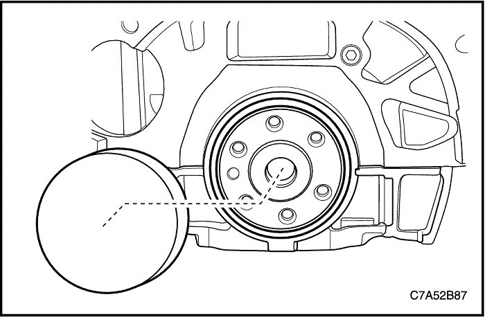
Install the camshaft front seal ring using by Camshaft Oil Seal Installer EN-48252.(a)
Notice : If the camshaft front oil seal is damaged, replace it with new oil seal. When installing the camshaft front oil seal to the oil pump, make the oil seal groove faced toward the oil pump case contact.
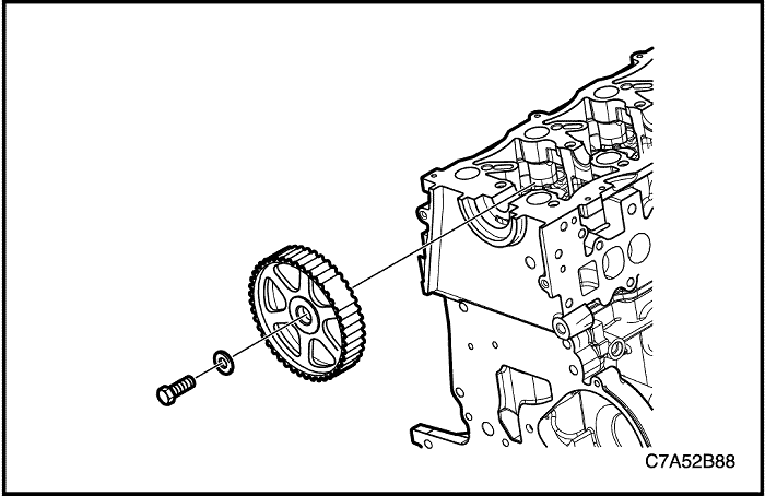
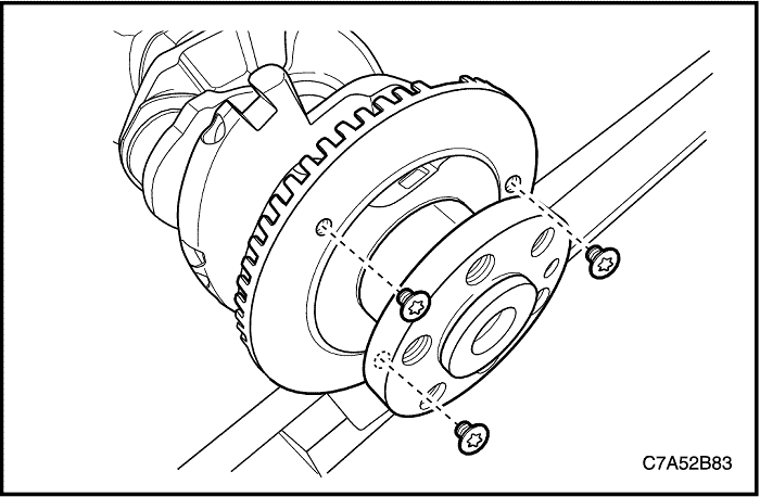
Install the camshaft sprocket.
Tighten
Tighten the camshaft sprocket bolt to 133 N•m (98.1 lb-ft).
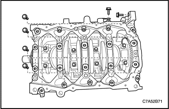
Insert the piston and connecting rod using by piston ring compressor EN-48249.
Install the connecting rod cap bolts.
Tighten
Tighten the connecting rod cap bolts to 25 N•m(18.4 lb-ft). Using the angular torque gauge KM-470-B, tighten the connecting rod cap bolts another 90 degrees.